® Setup Guide The Printronix P5000 series with DEC LG Emulation
The Printronix P5000 series with DEC LG Emulation Setup Guide ® 172292-001, Rev B
Trademark Acknowledgments Trademark Acknowledgments ANSI is a registered trademark of American National Standards Institute, Inc. Code V is a trademark of Quality Micro Systems. Chatillon is a trademark of John Chatillon & Sons, Inc. ENERGY STAR® is a registered trademark of the United States Environmental Protection Agency. As an ENERGY STAR® Partner, Printronix has determined that this product meets the ENERGY STAR® guidelines for energy efficiency. Ethernet is a trademark of Xerox Corporation.
Table of Contents 1 Overview............................................................... 9 About This Guide ................................................................................... 9 Warnings and Special Information .................................................. 9 Printing Conventions in This Guide ................................................. 9 Related Documents.........................................................................
Table of Contents Connect the Interface and Power Cables ..................................... 34 Install the Ribbon .......................................................................... 36 Load the Paper.............................................................................. 40 Power On the Printer..................................................................... 44 Set the Top-of-Form ...................................................................... 45 Test the Printer.................
Table of Contents HOST INTERFACE ........................................................................... 103 Serial Submenu........................................................................... 104 Parallel Submenu ........................................................................ 107 PRINTER CONTROL ........................................................................ 112 DIAGNOSTICS .................................................................................. 114 RIBBONMINDER......
Table of Contents New Ribbon................................................................................. 152 Ribbon Action.............................................................................. 153 RibbonMinder Fault ..................................................................... 154 Ribbon Size................................................................................. 155 Ribbon Adjust.............................................................................. 156 Fault Action ..
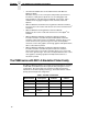
1 Overview About This Guide This Setup Guide is designed so you can quickly find the information you need to install and configure your Printronix DEC LG Emulation printer. Warnings and Special Information Read and comply with all information highlighted under special headings: WARNING CAUTION IMPORTANT Conditions that could harm you as well as damage the equipment. Conditions that could damage the printer or related equipment. Information vital to proper operation of the printer.
Chapter 1 The P5000 series with DEC LG Emulation • The Printronix P5000 series of Line Matrix Printers with DEC LG Operator’s Guide Describes the keys on the control panel and provides quick reference information on daily printer operations such as loading paper and replacing ribbons. This manual is provided with every printer, and is available in five languages: English, French, German, Italian and Spanish.
Printer Emulations Most line matrix printers have specialized architectures, which enable the printer to emulate, or behave like, another printer. These specialized architectures are restricted. Your printer, however, introduces an open architecture concept that is not available on any other line matrix printer. Your printer is very easy to use. The message display and lights on the control panel communicate with you directly and clearly.
Chapter 1 The P5000 series with DEC LG Emulation P5205 P5210 P5215 P5005 P5010 Figure 1.
Graphics Enhancement Option Graphics Enhancement Option The IGP/PGL and IGP/VGL emulations allow you to create and store forms, generate logos, bar codes, expanded characters, and create other graphics. Alphanumeric and bar code data are added as the form is printed. These emulations are available as factory-installed or field-installed options. For more information, contact your authorized service representative.
Chapter 1 The P5000 series with DEC LG Emulation Graphics and Vertical Formatting Several graphics and vertical formatting features are available: • Four built-in graphics generators: 1) IBM Proprinter III XL bit-image graphics 2) Epson FX dot graphics mode 3) P-Series Plot 4) LG Sixel Graphics • Programmable electronic vertical formatting provides rapid vertical paper movement to specified lines for printing repetitive and continuous forms.
Line Matrix Printing Line Matrix Printing Your printer creates characters and graphics by a printing technique called line matrix printing. Line matrix printing consists of printing patterns of ink dots on paper, an entire line at a time. Each text character is stored in memory as a pattern of dots on a logical grid called the dot matrix. (See Figure 2.) The actual ink dots are made by a row of hammer springs mounted on a shuttle that sweeps rapidly back and forth.
Chapter 1 The P5000 series with DEC LG Emulation After a line of characters is printed, hammer action stops while the paper advances to the first dot row of the next printable line. The number of rows allowed for line separation depends on the line spacing you select. Direction of Shuttle Movement Dot Row Start 1 2 3 4 5 6 7 8* 9* * 10 Number of rows is determined by line spacing. 11 n 1 2 One Text Line * ** Paper Feed Direction This row is used only for lowercase descenders.
2 Setting Up the Printer Before You Begin Read this chapter carefully before installing and operating the DEC LG Emulation printer. The printer is easy to install, but for your safety, and to protect valuable equipment, perform all the procedures in this chapter in the order presented. Power Requirements IMPORTANT It is recommended that printer power be supplied from a separate AC circuit protected at 10 amperes for 120 volts or 5 amperes for 230 volts at 50 or 60 Hertz.
Chapter 2 Before You Begin • Is located within the maximum allowable cable length to the host computer. This distance depends on the type of interface you plan to use, as shown in Table 2: Table 2. Interface Connections Interface Type Maximum Cable Length Centronics Parallel 5 meters (15 feet) IEEE 1284 Parallel 10 meters (32 feet) Dataproducts Parallel 12 meters (40 feet) Serial RS-232 15 meters (50 feet) Serial RS-422 1220 meters (4000 feet) Printer Cover Cabinet Rear Door 57.5 in. (146.
Select a Site 25 in. (63.5 cm.) 10.5 in. (26.67 cm.) 48.0 in. (122 cm.) 24.6 in. (62.48 cm.) 30 in. (76.2 cm.) Figure 5.
Chapter 2 Before You Begin Printer Component Locations Familiarize yourself with the names and locations of the printer components shown in Figure 6 before continuing with the rest of the installation procedure. Horizontal Tractor Lock Adjustment Knob Paper Scale Splined Shaft Paper Support Tractor Hammer Bank Cover and Ribbon Mask Vertical Position Knob Ribbon Loading Path Diagram Forms Thickness Lever Figure 6.
Remove the Cardboard Packing Remove the Shipping Restraints (Cabinet Model) Cardboard packing, protective foam, and tie wraps protect printer mechanisms from damage during shipment. This section describes how to remove these shipping restraints from the cabinet model before you operate the printer. Save the cardboard packing, foam blocks, and bubble wrap along with the other packing materials, since you may need to reinstall them. If it is necessary to move the printer, reinstall the shipping restraints.
Chapter 2 Remove the Shipping Restraints (Cabinet Model) Remove the Hammer Bank Protective Foam and Foam Strips Hammer Bank Protective Foam Foam Strips (2) Tractor Door Tractor Lock Figure 8. Removing the Hammer Bank Protective Foam and Foam Strips 1. Open the tractor doors. Push the tractor locks down. Slide the tractors and paper supports outward as far as they will go. The forms thickness lever should be in the fully open (raised) position. 2.
Remove the Platen Protective Foam Remove the Platen Protective Foam Platen Protective Foam Support Shaft Forms Thickness Lever Figure 9. Removing the Platen Protective Foam 1. Rotate the forms thickness lever downward to position “A”. 2. Rotate the platen protective foam toward the front of the printer and out from under the support shaft. Remove the platen protective foam.
Chapter 2 Remove the Shipping Restraints (Cabinet Model) Adjust the Paper Supports Tractor Door Paper Supports Tractor Door Figure 10. Adjusting Paper Supports 1. Slide paper supports inward until they are approximately four inches from the tractor door.
Release the Paper Chains Release the Paper Chains Tie Wrap Paper Chains Tie Wrap Plastic Bags Figure 11. Releasing the Paper Chains 1. Open the cabinet rear door. 2. Cut the tie wraps and release the paper chains from the bags at the top rear of the printer frame. Remove the tie wraps and bags. 3. Make sure each chain hangs freely, with no kinks or knots.
Chapter 2 Remove the Shipping Restraints (Cabinet Model) Remove the Tags Tie Wrap Passive Paper Stacker Tie Wrap Fence Tag Tag Figure 12. Remove Tag and Tie Wrap from Fence or Passive Paper Stacker 1. Remove the tie wrap and large red tag attached to the passive paper stacker. 2. Close the cabinet rear door. 3. Close the printer cover.
Attach the Control Panel Overlays Attach the Control Panel Overlays Figure 13. Attaching Control Panel Overlay 1. Choose the overlay labels in the appropriate language. 2. Open the printer cover, peel off the back of the overlay and apply to the control panel. Remove the Shipping Restraints (Pedestal Model) Protective films and foam blocks protect printer mechanisms from damage during shipment.
Chapter 2 Remove the Shipping Restraints (Pedestal Model) Remove the Hammer Bank Protective Foam Hammer Bank Protective Foam Tractor Door Tractor Lock Figure 14. Removing the Hammer Bank Protective Foam 1. Raise the printer cover. 2. Open the tractor doors. Push the tractor locks down. Slide the tractors and paper supports outward as far as they will go. The forms thickness lever should be raised (in the fully open position). 3. Remove the envelope that contains the sample configuration printout. 4.
Remove the Platen Protective Foam Remove the Platen Protective Foam Platen Protective Foam Support Shaft Forms Thickness Lever Figure 15. Removing Platen Protective Foam 1. Rotate the forms thickness lever downward to position “A”. 2. Rotate the platen protective foam toward the front of the printer and out from under the support shaft. Remove the platen protective foam.
Chapter 2 Remove the Shipping Restraints (Pedestal Model) Adjust the Paper Supports Tractor Door Paper Supports Tractor Door Figure 16. Adjusting Paper Supports 1. Slide paper supports inward until they are approximately four inches from the tractor door. 2. Close the printer cover.
Remove Tag Remove Tag Tie Wrap Tag Figure 17. Removing Tag from Cage Remove the tie wrap attached to the wireform paper path. It is marked with a large, red tag.
Chapter 2 Remove the Shipping Restraints (Pedestal Model) Attach the Output Basket Figure 18. Attaching the Output Basket 1. Place the output basket in the holes in the back of the printer. 2. Screw the ground wire attached to the output basket to the printer.
Attach the Control Panel Overlays Attach the Control Panel Overlays Figure 19. Attaching Control Panel Overlays 1. Choose the overlay labels in the appropriate language. 2. Open the printer cover and insert overlay labels by sliding them behind the control panel assembly in the appropriate place.
Chapter 2 Install Basic Components Install Basic Components The following section gives instructions on essential procedures which keep your printer operational on a day-to-day basis. Connect the Interface and Power Cables Before you connect the interface and power cables, verify the voltage source at the printer site conforms to the requirements specified on page 17. Make sure the printer power switch is set to OFF (see Figure 21).
Connect the Interface and Power Cables Cabinet Model Pedestal Model Host Interface Connectors I/O Cover OFF/ON Host Interface Connectors AC Power Connector Cable-Routing Notch (2) Power Switch AC Power Cable AC Power Connector FG QHZLR Figure 21. Interface and Power Locations 1. Make sure the printer power switch is set to OFF (see Figure 21). Connect the (customer-supplied) interface cable from the host computer to the appropriate printer interface connector (see Figure 20).
Chapter 2 Install Basic Components Install the Ribbon Figure 22. Ribbon Path Diagram Location 1. Refer to the ribbon path diagram molded onto the shuttle cover. 55cabopn MAy 1, 2001 Figure 23. Opening the Printer Cover 2. Verify that the printer is offline and that the printer cover is open.
Install the Ribbon Tractor Door Forms Thickness Lever Figure 24. Forms Thickness Lever 3. Raise the forms thickness lever as far as it will go. 4. Swing open the tractor doors. Hub Latch Figure 25. Right Hub Latch 5. Squeeze the right hub latch and place the full spool on the right hub. Be sure the ribbon feeds off the outside of the spool. Press the spool down until the hub latch snaps into place.
Chapter 2 Install Basic Components Paper Hammer Bank Cover Ribbon Mask Ribbon Mask Hammer Bank Cover Platen Ribbon Front of Printer Hammer Tip 55rib2a April 27, 2001 Ribbon Guide Figure 26. Ribbon Path 6. Thread the ribbon around the ribbon guide and along the ribbon path. Refer to the ribbon path diagram on the shuttle cover. Be sure to thread the ribbon between the hammer bank cover and the ribbon mask. CAUTION 38 The ribbon must not be twisted.
Install the Ribbon Cabinet Model 55rib3 August 15, 2000 Pedestal Model p55rib3 May 1, 2001 Figure 27. Left Ribbon Hub 7. Place the empty spool on the left hub. Press the spool down until the hub latch snaps into place. Turn the spool by hand to make sure the ribbon tracks correctly in the ribbon path and ribbon guides.
Chapter 2 Install Basic Components Load the Paper This section explains how to load paper for the first time. If you are loading paper over existing paper, see the Operator’s Guide. Tractor Door Forms Thickness Lever Figure 28. Forms Thickness Lever and Tractor Doors When you start this procedure, verify that the printer cover is open, the forms thickness lever is raised, and the tractor doors are open. EDGE OF PAPER BOX Figure 29. Paper Supply Label Location 1.
Load the Paper Paper Slot is 8 inches below printer base Paper Slot Figure 30. Paper Slot Location 2. Feed the paper up through the paper slot. Hold the paper in place with one hand (to prevent it from slipping down through the paper slot) while pulling it through from above with your other hand. Tractor Door Paper Tractor Lock Ribbon Path Diagram Figure 31. Loading Paper Onto the Left Tractor Sprockets 3.
Chapter 2 Install Basic Components Paper Scale Figure 32. Paper Scale 4. If adjustment is necessary, unlock the left tractor. Slide the tractor until it is directly to the left of the number “1” on the paper scale and lock it. (You can also use the paper scale to count columns.) CAUTION To avoid damage to the printer caused by printing on the platen, always position the left tractor unit directly to the left of the “1” mark on the paper scale. Splined Shaft Figure 33.
Load the Paper Horizontal Adjustment Knob Figure 34. Horizontal Adjustment Knob 8. After both tractors are secured, you may use the horizontal adjustment knob to make fine horizontal paper adjustments. A Thin Paper B Medium Paper C Thick Paper Figure 35. Lowering the Forms Thickness Lever 9. Lower the forms thickness lever. Set it to match the paper thickness. The A-B-C scale corresponds approximately to 1-, 3-, and 6-part paper thickness. Adjust until you have the desired print quality.
Chapter 2 Install Basic Components Power On the Printer Following are instructions for powering on the printer after you have installed the ribbon and loaded paper. Figure 36. The Power Switch 1. When you start this procedure, verify that paper and ribbon are installed, the forms thickness lever is lowered, and the tractor doors are closed. This prevents a “LOAD PAPER” or “CLOSE PLATEN” error message from displaying after the printer is powered on. 2. Set the power switch to the ON position (Figure 36).
Set the Top-of-Form Set the Top-of-Form Following are instructions for setting the top-of-form after you have powered on the printer. Paper Path Figure 37. The Lower Paper Guide 1. When you start this procedure, verify that the printer is in offline mode, with the printer cover open and the forms thickness lever lowered. 2. Press the FF key several times to ensure the paper feeds properly beyond the tractors and over the lower paper path.
Chapter 2 Install Basic Components Forms Thickness Lever Figure 38. Raising the Forms Thickness Lever 3. Raise the forms thickness lever as far as it will go. This allows you to turn the vertical position knob freely in order to align the top-of-form. TOF Indicator Perforation Vertical Position Knob Figure 39. Aligning the Top-of-Form 4. Locate the TOF indicator. It is the small tab located on the tractor doors. 5.
Set the Top-of-Form A Thin Paper B Medium Paper C Thick Paper Figure 40. Lowering the Forms Thickness Lever 6. Lower the forms thickness lever. Set it to match the paper thickness. The A-B-C scale corresponds approximately to 1-, 3-, and 6-part paper thickness. Adjust until you have the desired print quality. NOTE: Do not set the forms thickness lever too tightly; excessive friction can cause paper jams, ribbon jams with potential for ribbon damage, smeared ink, or wavy print.
Chapter 2 Install Basic Components Test the Printer Table 3. Printer Test Procedure Step 1. 2. 3. Key Result Notes Make sure that the printer top cover is open and the forms thickness lever is lowered. ONLINE + OFFLINE CONFIG. CONTROL The printer must be off line for testing. ENTER SWITCH UNLOCKED Allows you to make configuration changes. OFFLINE CONFIG. CONTROL 4. UNTIL 5. DIAGNOSTICS Printer Tests 6. Printer Tests Shift Recycle* 7. R/S 8. R/S 9. 10.
3 Configuring the Printer Overview IMPORTANT Configuration directly affects printer operation. Do not change the configuration of your printer until you are thoroughly familiar with the procedures in this chapter. In order to print data, the printer must respond correctly to signals and commands received from the host computer.
Chapter 3 Overview OFFLINE CONFIG. CONTROL Load Config. Save Config. Print Config. Delete Config. Power-Up Config. Protect Configs.
Changing and Saving Parameter Settings Changing and Saving Parameter Settings You can change a parameter setting, such as line spacing or forms length, by pressing keys on the control panel or by sending emulation control codes in the host data stream. Refer to the appropriate Programmer’s Reference Manual for information about control codes. When you change a parameter, it is active as long as the printer is on or until changed.
Chapter 3 Overview Operating Modes The printer has three operating modes: online mode, offline mode, and fault mode. • Online Mode. When the printer is online, it is controlled by the host computer and prints data sent by the host computer. • Offline Mode. In offline mode, communication with the host is interrupted so that you can load paper, change ribbons, or test and configure the printer. • Fault Mode.
Unlocking and Locking the ENTER Key Unlocking and Locking the ENTER Key The ENTER key is locked by default, to prevent you from accidentally changing the printer configuration. You should generally unlock the ENTER key directly before you begin configuration using the menus; once the changes are made, relock the ENTER key to secure your new settings. To unlock the ENTER key, place the printer in the offline mode and press UP and DOWN simultaneously.
Chapter 3 Overview Italic PrintDisable Slashed ZeroDisable Page Format Margins Left Margin0 columns Right Margin0 columns Bottom Margin0 lines Perforation SkipDisable Form Length Abs. Length IN11.0 inches Abs. Length MM279.4 mm Function of lines66 lines Form Width Abs. Width IN13.6 inches Abs. Width MM345.
Example Changing Parameters A configuration consists of several parameters. The default factory configuration has a starting set of parameters. Your print jobs may require different parameter settings from the default that is provided. This section provides an example procedure for changing and saving individual parameter values. Example The following procedure shows how to change and save the settings for the Unidirectional option.
Chapter 3 Changing Parameters Table 4. Parameter Change Example Procedure (continued) Step Key 4. UNTIL 5. Notes OFFLINE PRINTER CONTROL PRINTER CONTROL Unidirectional 6. Unidirectional Disable* 7. OR 8. Result ENTER Unidirectional Enable Unidirectional Enable* Cycle through the choices. An asterisk (*) indicates this choice is active. TO SAVE YOUR CHANGES AS A CONFIGURATION THAT IS STORED IN MEMORY: 1. UNTIL 2. 3. UNTIL OFFLINE PRINTER CONTROL OFFLINE CONFIG.
Saving Your New Configuration Saving Your New Configuration * = Factory Default CONFIG. CONTROL Load Config. Save Config. Print Config. Delete Config. Power-Up Config. Protect Configs. 1 2 3 4 5 6 7 8 After changing all of the necessary parameters, it is recommended you save them as a configuration that can be stored and loaded later for future use. If you do not save your configuration before you power off the printer, all of your parameter changes will be erased. The Save Config.
Chapter 3 Changing Parameters Table 5. Saving Configurations Step 1. 2. 3. Key Result Notes If you are already in the configuration menu, go to step 5. ONLINE OFFLINE CONFIG. CONTROL ENTER SWITCH UNLOCKED + Allows you to make configuration changes. OFFLINE CONFIG. CONTROL 4. CONFIG. CONTROL Load Config. 5. UNTIL 6. CONFIG. CONTROL Save Config. Save Config. 1* 7. OR Save Config. 2 Press until the desired number (1-8) displays.
Deleting Your Configuration Deleting Your Configuration * = Factory Default CONFIG. CONTROL Load Config. Save Config. Print Config. Delete Config. Power-Up Config. Protect Configs. 1* 2 3 4 5 6 7 8 If you wish to delete a configuration from memory, select the appropriate configuration number from the menu and press ENTER. The Protect Configs. parameter must be set to disable before you may delete a configuration. Once you delete a configuration the Protect Configs.
Chapter 3 Changing Parameters Table 6. Deleting Configurations Step 1. 2. 3. Key Result Notes Make sure the printer is on. Raise the printer cover. ONLINE OFFLINE CONFIG. CONTROL ENTER SWITCH UNLOCKED + Allows you to make configuration changes. OFFLINE CONFIG. CONTROL 4. CONFIG. CONTROL Load Config. 5. UNTIL 6. Delete Config. 1* 7. OR 8. CONFIG. CONTROL Delete Config. ENTER Delete Config. 3 Deleting Configuration Press until the desired number (1-8) displays.
Protecting Your Configurations Protecting Your Configurations * = Factory Default CONFIG. CONTROL Load Config. Save Config. Print Config. Delete Config. Power-Up Config. Protect Configs. Enable* Disable In order to save or delete a configuration you must set the Protect Configs. option to disable. The Protect Configs. selection will automatically return to enable once a configuration is saved or deleted. Printing the Current Configuration * = Factory Default CONFIG. CONTROL Load Config.
Chapter 3 Changing Parameters Table 7. Printing Configurations Step 1. 2. 3. Key Result Notes Make sure the printer is on. Raise the printer cover. ONLINE OFFLINE CONFIG. CONTROL ENTER SWITCH UNLOCKED + Allows you to make configuration changes. OFFLINE CONFIG. CONTROL 4. CONFIG. CONTROL Load Config. 5. UNTIL 6. Print Config. Current* 7. OR 8. 9. 10. 11. 12. 62 CONFIG. CONTROL Print Config. ENTER Print Config. All Press until the desired option displays. OFFLINE CONFIG.
Loading Configuration Values Loading Configuration Values * = Factory Default CONFIG. CONTROL Load Config. Save Config. Print Config. Delete Config. Power-Up Config. Protect Configs. 0* 1 2 3 4 5 6 7 8 You can load any of the eight customized configurations or the factory default configuration. The loaded configuration remains active as long as the printer is on. If you power off the printer, the power-up configuration will load.
Chapter 3 Changing Parameters Table 8. Loading Configurations Step 1. 2. 3. Key Result Notes Make sure the printer is on. Raise the printer cover. ONLINE + OFFLINE CONFIG. CONTROL ENTER SWITCH UNLOCKED Allows you to make configuration changes. OFFLINE CONFIG. CONTROL 4. CONFIG. CONTROL Load Config. 5. Load Config. 1* 6. OR 7. ENTER Load Config. 4 Loading Saved Configuration Load Config. 4* 8. 9. 10. 64 + ONLINE ENTER SWITCH LOCKED Press until the desired number (1-8) displays.
The Power-Up Configuration The Power-Up Configuration * = Factory Default CONFIG. CONTROL Load Config. Save Config. Print Config. Delete Config. Power-Up Config. Protect Configs. 0* 1 2 3 4 5 6 7 8 When you power on the printer for the first time, it loads configuration 0, the factory default configuration. If you save a configuration, such as configuration 1, and turn the power off and then back on, the printer will load the designated power-up configuration, not the last saved configuration.
Chapter 3 Changing Parameters Table 9. Setting The Power-Up Configuration Step 1. 2. 3. Key Result Notes Make sure the printer is on. Raise the printer cover. ONLINE OFFLINE CONFIG. CONTROL ENTER SWITCH UNLOCKED + Allows you to make configuration changes. OFFLINE CONFIG. CONTROL 4. CONFIG. CONTROL Load Config. 5. UNTIL 6. Power-Up Config. 0* 7. OR 8. 9. 10. 11. 66 CONFIG. CONTROL Power-Up Config. ENTER + ONLINE Power-Up Config. 6 Press until the desired number (1-8) displays.
4 The Configuration Menus Overview Once you have familiarized yourself with the configuration process using the tutorial information in Chapter 3, you are ready to complete your configuration of the printer. This chapter provides descriptions for each parameter. Figure 44 shows the main configuration menu. Configuration Main Menu Brief descriptions follow for the first-level configuration menu options: • CONFIG. CONTROL.
Chapter 4 Overview OFFLINE CONFIG. CONTROL (see page 70) Load Config. 0* - 8 Save Config. 1* - 8 Print Config. Current* Factory Power-Up All 1-8 Delete Config. 1* - 8 Power-Up Config. 0* - 8 Protect Configs.
Configuration Main Menu HOST INTERFACE (see page 103) Serial* Interface Type RS-232*/RS-422 Data Protocol XON/XOFF* ETX/ACK ACK/NAK DTR Baud Rate 600, 1200, 2400 4800, 9600*, 19200, 38400 57600, 115200 Word Length 8* or 7 Stop Bits 1* or 2 Parity None*, Odd Even, Mark Sense Data Term Ready True* On-Line and BNF Off-Line or BF False Request to Send True* On-Line and BNF Off-Line or BF False Buffer Size in K 8* (1-16) PRINTER CONTROL (see page 112) Parallel Centronics Data Bit 8 Enable*/Disable Data Polarit
Chapter 4 CONFIG. CONTROL CONFIG. CONTROL Menu * = Factory Default CONFIG. CONTROL Load Config. 0* 1 2 3 4 5 6 7 8 Save Config. 1* 2 3 4 5 6 7 8 Print Config. Current* Factory Power-Up All 1 2 3 4 5 6 7 8 Delete Config. 1* 2 3 4 5 6 7 8 Power-Up Config. 0* 1 2 3 4 5 6 7 8 To view options, press: Protect Configs. Enable* Disable ⇓ Down ⇑ Up ⇒ Next ⇐ Prev To select an option, press ENTER. To return to main menu, press CLEAR. To exit menu, press ONLINE. * = Default Setting The CONFIG.
Menu Save Config. This option allows you to save up to eight unique configurations to meet different print job requirements. This eliminates the need to change the parameter settings for each new job. The configurations are stored in memory, and will not be lost if you turn off the printer. Configuration 0 is a factory-preset configuration, which cannot be changed or saved. See page 55 for a fuller description and sample procedure. The Protect Configs.
Chapter 4 ACTIVE EMULATION ACTIVE EMULATION ACTIVE EMULATION LG* LinePrinter+ IGP/PGL & LP+1 IGP/VGL & LP+1 To view options, press: ⇓ Down ⇑ Up ⇒ Next ⇐ Prev To select an option, press ENTER. To return to main menu, press CLEAR. To exit menu, press ONLINE. 1 = if installed * = Default Setting The ACTIVE EMULATION menu allows you to select the emulation to be used with your DEC LG Emulation printer. Digital LG is the default active emulation.
Menu EMULATION EMULATION LG* LinePrinter+ IGP/PGL1 IGP/VGL1 page 74 page 78 page 89 page 94 To view options, press: ⇓ Down ⇑ Up ⇒ Next ⇐ Prev To select an option, press ENTER. To return to main menu, press CLEAR. To exit menu, press ONLINE. 1Optional Emulation * = Default Setting The EMULATION menu is the gateway to configuring the emulations available with the DEC LG Emulation.
Chapter 4 Digital LG Digital LG Submenu * = Factory Default EMULATION LG Font Vert. Forms Bot.
Submenu Font Select a default font style and character set for the LG emulation, as follows: • Style. This option allows you to specify a print quality that includes a characters per inch (cpi) and lines per inch (lpi) setting, in the format Type cpi lpi. The default setting is DP 10 6 (Data Processing, 10 cpi, 6 lpi).
Chapter 4 Digital LG Autowrap • No. The default. Any print data received past the forms width setting is discarded. • Yes. An automatic carriage return and line feed is performed when data is received past the forms width setting. CR (Carriage Return) The CR option controls the action of the printer when it receives a Carriage Return code (hex 0D) from the host computer. • • CR = CR. The default. No line feed is added to a Carriage Return. CR = CR + LF.
Submenu Print Mode Opt When enabled, this option affects the SPI, SHS, and DECSHORP commands. The printer will no longer be forced into these commands and print speed improves significantly when in portrait orientation. For SHS and DECSHORP, the character size will change with the selected pitch. In addition, SGR attributes such as bold, crossed-out, and italics, will be done in print mode with greater efficiency. • • Enable. The default. Enables the print mode option. Disable.
Chapter 4 LinePrinter+ LinePrinter+ * = Factory Default EMULATION LinePrinter+ Printer Protocol Print Char. Set CPI/LPI Select Font Attributes Select CPI 10.0 CPI* 12.0 CPI 13.3 CPI 15.0 CPI 17.1 CPI 20.0 CPI Select LPI 6.0 LPI* 8.0 LPI 10.3 LPI Typeface (see next page) Data Proc.* NLQ OCR-A OCR-B High Speed NLQ Sans Serif Prop.
Submenu * = Factory Default Page Format (from page 78) Margins Perforation Skip Left Margin 0* columns (0-369) Right Margin 0* columns (0-369) Bottom Margin 0* lines (0-451) Disable* 1/2 inch 2/3 inch 5/6 inch 1 inch Form Length Form Width Abs. Length IN Abs. Width IN 11.0* inches 13.6* inches (0.1-24) (0.1-13.6) Abs. Length MM Abs. Width MM 279.4* millimeters 345.4* millimeters (0.1-609.6) (0.1-345.4) Funct. of Lines Funct.
Chapter 4 LinePrinter+ • High Speed. A draft quality font printing at 120 dpi horizontally and 48 dpi vertically. The width of the font varies with the cpi. • NLQ Sans Serif. A high quality font printing at 180 dpi horizontally and 96 dpi vertically. This font prints without serifs. The width of the font varies with the cpi. Proportional Spacing Each printed character is contained inside a character cell. The width of the character cell includes the character and the space around the character.
Submenu Page Format Margins • Right Margin. Set in columns. Column zero is defined as the far right edge of the page, and column numbering increments from right to left. • Left Margin. Set in columns. Column zero is defined as the far left edge of the page, and column numbering increments from left to right. • Bottom Margin. Defined in lines, starting from line zero at the bottom of the page and incrementing from the bottom up. Perforation Skip • • Disable. Allows printing on page perforation.
Chapter 4 LinePrinter+ Proprinter XL Emulation * = Factory Default Printer Protocol (from page 78) Proprinter XL Define CR Code CR = CR* CR = CR + LF Auto LF Enable* Disable Define LF Code LF = LF* LF = CR + LF FF Valid at TOF Enable* Disable Character Set Code Page 437* Code Page 850 OCR-A OCR-B Code Page 210 Code Page 220 Code Page 852 Code Page 855 Code Page 857 Code Page 862 Code Page 866 Lithuanian 1 Lithuanian 2 Hebrew New Hebrew DEC Hebrew Old Latin 9 8859-15 Alt.
Proprinter XL Emulation Define LF Code • LF = LF. Does not perform an automatic carriage return when a line feed command is received. The next print position will be the current print position of the next line. • LF = CR + LF. Forces an automatic carriage return with each line feed command received. The next print position is print position 1 of the next line. FF Valid at TOF • Enable. Performs a form feed when the host sends a Form Feed command and the printer is at the top of form. • Disable.
Chapter 4 LinePrinter+ Epson FX Emulation * = Factory Default Printer Protocol (from page 78) Epson FX Define CR Code CR = CR* CR = CR + LF Auto LF Enable* Disable Define LF Code LF = LF* LF = CR + LF Printer Select Disable* Enable Character Set 20 CPI Condensed Epson Set* Enable* ASCII (USA)* Disable French German English Danish I Swedish Italian Spanish I Japanese Norwegian Danish II Spanish II Latin Am I French Canadian Latin Am II OCR-A OCR-B Code Page 210 Code Page 220 Code Page 852 Code Pa
Epson FX Emulation Auto LF This option defines the printer actions when print data is received past the forms width setting. • Enable. Performs an automatic carriage return and line feed when data is received past the forms width. • Disable. Discards any data past the forms width. Define LF Code The Define LF Code option controls the action of the printer when it receives a Line Feed code (hex 0A) from the host computer.
Chapter 4 LinePrinter+ P-Series Emulation * = Factory Default Printer Protocol (from page 78) P-Series Control Code 06 6.0 LPI 8.0 LPI* 10.3 LPI Select SFCC 1* (00-7F hex) Control Code 08 Elongated* Backspace EVFU Select Enable* Disable IBM PC* Disable* Enable Alt.
P-Series Emulation Control Code 06 Control Code 06 defines the function of ASCII code hex 06 (ACK). You can select an alternate line spacing of 6, 8 or 10.3 LPI. Control Code 08 Control Code 08 defines the function of ASCII code hex 08 (BS). You can define the code to output an elongated character or a backspace. Define CR Code This option controls the action of the printer when it receives a Carriage Return code (hex 0D) from the host computer.
Chapter 4 LinePrinter+ Select SFCC This parameter allows you to select which ASCII codes will function as the Special Function Control Code (SFCC) command delimiter. P-Series codes can use hex 00 through hex 7F. Options include the following: • • • • • ESC (hex 1B) SOH (hex 01) ETX (hex 03) CIRCUMFLEX (hex 5E)—also called caret (^) TILDE (hex 7E)—(~) NOTE: SOH, ETX and ESC are non-printables.
Submenu IGP/PGL Emulation The IGP/PGL emulation can be configured either through the printer’s front panel or from the host computer with control codes. For a detailed description of configuration with control codes, see the DEC LG Emulation IGP/PGL Programmer’s Reference Manual. For information on configuring the emulation through the printer’s front panel, see the submenu below and the parameter descriptions that follow.
Chapter 4 IGP/PGL Emulation Define CR Code (Carriage Return) This parameter forces the printer to insert an automatic Line Feed code into the data stream whenever a Carriage Return code occurs. This is to be used only if the host computer does not send Line Feeds to the printer. • CR = CR. Does not perform a line feed. The next print position will be print position 1 of the current line. • CR = CR + LF. Performs an automatic line feed.
Submenu CR Edit This parameter determines if a carriage return will be followed by a line feed. • Disable. The printer ignores all carriage returns that are not followed by line feeds. • Enable. The printer processes all carriage returns, even for those that are not followed by line feeds. Select Font This parameter allows you to select a font for the IGP/PGL feature. The default is 0, which is U.S. ASCII. The following values are valid choices: 0 1 2 3 4 5 6 7 8 9 10 11 32 33 U.S.
Chapter 4 IGP/PGL Emulation Skip Command Prefix This parameter determines if the printer will print any data before an IGP/PGL command is received. • Enable. The printer ignores all data on the current line before an IGP/ PGL command. • Disable. The printer will print all data on the current line before an IGP/ PGL command. Power On IGP/PGL You can set the IGP/PGL feature so that it is enabled or disabled when the printer is powered on. • Enable.
Submenu Ignore Character Ignore Mode This parameter instructs the IGP/PGL to ignore the character selected under the Select Character menu. • • Disable. The IGP/PGL does not ignore any characters. Enable. The IGP/PGL ignores the characters specified in the Select Character menu. Select Character Instructs the IGP/PGL which decimal character (0-255) to ignore from the host. IGP100 Compatbl. This option instructs the IGP/PGL to behave similar to the IGP-100 with respect to certain commands.
Chapter 4 IGP/VGL Emulation IGP/VGL Emulation The IGP/VGL emulation can be configured either through the printer’s front panel or from the host computer with control codes. For a detailed description of configuration with control codes, see the IGP/VGL Programmer’s Reference Manual. For information on configuring the emulation through the printer’s front panel, see the submenu below and the parameter descriptions that follow.
Submenu * = Factory Default Graphics Options (from page 94) Slash 0 Disable* Enable UPC Descenders Enable* Disable Absorb After ^PN Disable* Enable Ignore Dots Append Rotated Disable* Enable Disable* Enable Rot.
Chapter 4 IGP/VGL Emulation Power Up ^F • • Disable. The default. Enable. Selects free format mode as the power-up default, and selects the graphics mode ^PY as the power-up default. Free format causes the IGP/VGL to ignore carriage returns, line feeds and all characters below hex 20 sent from the host. Power Up ^PY • • Disable. The default. Enable. Selects the graphics mode ^PY as the power-up default. LPI The number of lines to be printed per inch.
Submenu True Vert 1/10 • Enable. A vertical 1/10 of an inch parameter is used as 1/10 of an inch. Rounding occurs to the nearest 1/72 of an inch. This can cause vertical moves that have the same value to differ by ± 1/72 of an inch. • Disable. A vertical 1/10 of an inch parameter is used as 7/72 of an inch. The absolute move is slightly smaller than expected. For example, a one inch move would be 70/72 of an inch. Vertical moves that have the same value will be identical in length.
Chapter 4 IGP/VGL Emulation Dark Barcode • Disable. Dark mode printing will only occur if the dark mode command is sent before the bar code command. • Enable. Bar codes will be printed in dark mode no matter what the dark mode is set for. Width Limit When enabled, the system will limit the length and width for expanded characters to a limit shown in Table 10, which shows the maximum width allowed for a specific height in the range of 00 through 40 (0.0 through 4.0 inches). Table 10.
Submenu Absorb After ^PN • Disable. All line terminators that immediately follow the ^PN command are sent to the printer and processed. • Enable. All line terminators that immediately follow the ^PN command are ignored. IGP 110 Compatbl. This option instructs the IGP/VGL to behave similar to the IGP-110 with respect to certain commands. All new users with new applications should select the “Disable” option. Selecting this mode insures the printer will behave as described in this manual. • • Disable.
Chapter 4 IGP/VGL Emulation NOTE: When Barcode Errors is disabled, the IGP/VGL emulation will try to make the best use of invalid data by either truncating extra digits or adding zeros to the end of bar code data to meet minimum data length requirements for some bar codes. Not all errors will be corrected. Ignore / DB8 Setup Following are several options which define character filtering and data bit 8. Ignore Chars • • Disable. Character filtering is not enabled. • Char 2.
Submenu Font Set This parameter allows you to select a font for the IGP/VGL feature. The default is 0, which is U.S. ASCII. The following values are valid choices: 0 1 2 3 4 5 6 7 8 9 10 11 32 33 U.S. ASCII German Swedish Danish Norwegian Finnish English Dutch French Spanish Italian Turkish Code Page 437 Code Page 850 Values 12-23 are undefined and will default to 0. You can set values 24-31 to specific fonts; refer to the User Set command in the IGP/VGL Programmer’s Reference Guide.
Chapter 4 MAINT / MISC MAINT / MISC Menu MAINT/MISC Hex Dump Mode Disable* Enable Power-up State Online* Offline Display Language English* German French Italian Spanish To view options, press: ⇓ Down ⇑ Up ⇒ Next ⇐ Prev To select an option, press ENTER. To return to main menu, press CLEAR. To exit menu, press ONLINE.
Menu HOST INTERFACE IMPORTANT The printer will not print unless the type of interface selected from the Host Interface Menu matches the type of interface in your host computer. The interface in your host computer is the one that connects to the data cable of the printer. For example, if the interface in your computer is a serial interface, then the serial interface must be selected from the Host Interface Menu in the printer.
Chapter 4 HOST INTERFACE Serial Submenu IMPORTANT The serial parameters in the printer must be set the same as the serial interface in the host computer. Otherwise, the printer might not work online, and data characters from the computer might not print or might print as “garbled” text.
Serial Submenu If the host keeps sending data after an XOFF is sent, the printer firmware will continue to send an XOFF for every 16 characters received. When cleared, the printer will resume receiving data (XON). The data does not have any End of Text codes; XON / XOFF is a non-block protocol. • ETX / ACK. End of Text / Acknowledge. The host controls the flow of communication to the printer by sending a block of data and ending the block with an End of Text (ETX) signal.
Chapter 4 HOST INTERFACE Data Terminal Ready This configuration is part of hardware flow control and determines when the Data Terminal Ready (DTR) signal is generated. This signal indicates whether or not the printer is ready to receive data. • • True. Continuously asserts the DTR signal (the default). • Off-Line or BF (buffer full). Asserts the DTR signal when the printer is offline or the internal serial buffer is full. • False. Never asserts the DTR signal. On-Line and BNF (buffer not full).
Parallel Submenu Parallel Submenu Centronics Interface IMPORTANT The Centronics parameters in the printer must be set the same as the Centronics interface in the host computer. Otherwise, the printer might not work online, and data characters from the computer might not print or might print as “garbled” text.
Chapter 4 HOST INTERFACE Strobe Polarity The Strobe Polarity must be set to match the data strobe polarity of your host computer. When the host computer sends a data strobe signal to the printer, this enables the printer to read the data bus. • • Standard. Does not expect the data strobe signal to be inverted. Inverted. Expects the host computer to invert the data strobe signal. Response Polarity The Response Polarity parameter must be set to match the response polarity of your host computer.
Parallel Submenu Dataproducts Submenu IMPORTANT The Dataproducts parameters in the printer must be set the same as the Dataproducts interface in the host computer. Otherwise, the printer might not work online, and data characters from the computer might not print or might print as “garbled” text. * = Factory Default Parallel (from page 103) Dataproducts Data Bit 8 Enable* Disable PI Ignored Enable* Disable Data Polarity Standard* Inverted Data Request Pol.
Chapter 4 HOST INTERFACE Data Request Polarity The Data Request Polarity parameter must be set to match the data request polarity of your host computer. • • Standard. Does not invert the request signal. Inverted. Inverts the request signal sent to the host computer. Strobe Polarity The Strobe Polarity must be set to match the data strobe polarity of your host computer. When the host computer sends a data strobe signal to the printer, this enables the printer to read the data bus. • • Standard.
Parallel Submenu Bidirectional Submenu The IEEE 1284 (Bidirectional) interface is faster and more versatile than Centronics and supports bidirectional communication. Chapter 5 discusses the available modes (Compatibility, Nibble, and Byte) in more detail. * = Factory Default Parallel (from page 103) Bidirectional Buffer Size in K 8* (1-16) Buffer Size in K This option configures the amount of memory allocated for the 1284 parallel port buffer.
Chapter 4 PRINTER CONTROL PRINTER CONTROL The printer control menu allows you to choose the printer’s behavior. Options on this menu, as shown below, are described in the following pages. PRINTER CONTROL Unidirectional Disable* Enable PMD Fault Enable* Disable Slow Paper Slew Disable* Enable Power Saver Time 15 mins.* (5 sec.-60 min.) To view options, press: ⇓ Down ⇑ Up ⇒ Next ⇐ Prev To select an option, press ENTER. To return to main menu, press CLEAR. To exit menu, press ONLINE.
Parallel Submenu PMD (Paper Motion Detection) Fault CAUTION • Enable. If a paper jam occurs, an audible alarm beeps, “CLEAR PAPER JAM” appears on the message display, and the printer stops printing. • Disable. You should disable PMD only if special paper requires it. Once PMD is disabled, paper motion is not monitored. If a paper jam occurs, the printer ignores the condition and continues to print, possibly causing severe damage to the printer.
Chapter 4 DIAGNOSTICS DIAGNOSTICS The diagnostics menu allows you to choose the diagnostics tests to be run and provides you with important system information. Options on this menu, as shown below, are described in the following pages. DIAGNOSTICS Printer Tests Test Width Shift Recycle* Full Width* All E’s 80 columns E’s + TOF All H’s All Underlines All Black Shuttle Slow Shuttle Fast Shuttle Only Phase Printer 217* (500 lpm) 123* (1000 lpm) 62* (1500 lpm) 1 to 2000 Paperout Adj.
Parallel Submenu • All H’s. A pattern of all uppercase H’s used to detect missing characters, misplaced dots, smeared characters, or improper phasing. • All Underlines. An underline pattern useful for identifying hammer bank misalignment. • All Black. A condition where all dot positions are printed, creating a solid black band. • Shuttle Slow. Verifies proper operation by exercising shuttle and ribbon motion at low speed. • Shuttle Fast.
Chapter 4 DIAGNOSTICS Print Statistics You can view various printer statistics, such as hours of usage, and refer to these figures for preventive maintenance purposes. Printer statistics accumulate continuously; they do not reset when you turn off the printer. All of the printer statistics are set to zero at the factory after burn-in testing. 116 • On. The cumulative time in hours the printer has been powered on. The range is 0 to 30,000 hours. • Print.
Parallel Submenu RIBBONMINDER RibbonMinder™ monitors ink consumption to ensure quality printing. The “RibbonMinder” chapter explains how to use this feature and its options in more detail. RIBBON MINDER New Ribbon Ribbon Action Press ENTER to reset ribbon life to 100%. A new ribbon must be installed after setting the ribbon life to 100%.
Chapter 4 RIBBONMINDER Ribbon Size The standard ribbon size is 100 yards in the cabinet model and 60 yards in the pedestal model; these are the factory default settings. You can use the Ribbon Size option to specify the ribbon length in increments of one yard with a maximum of 255 yards. Ribbon Adjust Enables you to print more or less pages before the display reaches 0%.
5 Interfaces Overview This chapter describes the interfaces provided with the printer. The printer interface is the point where the data line from the host computer plugs into the printer. The interface processes all communication signals and data to and from the host computer. It consists of a printed circuit board assembly (PCBA) and a connector for the data cable from the host computer. Communication signals and data may be sent over parallel or serial lines.
Chapter 5 Dataproducts Parallel Interface Dataproducts Parallel Interface The Dataproducts parallel interface allows the printer to operate with a 50-pin Amplimite (AMP) HDH-20 data cable connector. The length of the data cable from the host computer to the printer must not exceed 40 feet (12 meters). Table 11.
Dataproducts Parallel Interface Configuration edge of the strobe signal can be configured as leading, middle (default), or trailing. Paper Instruction (PI). Carries a DVFU signal from the host with the same timing and polarity as the data lines. Ready. Carries a high true signal from the printer when AC power and DC voltages are present, paper is loaded properly, and the printer is not in a check condition. Online.
Chapter 5 Centronics Parallel Interface Centronics Parallel Interface The Centronics interface enables the printer to operate with controllers designed for buffered Centronics printers. The length of the data cable from the host computer to the printer must not exceed 15 feet (5 meters). Table 12.
Centronics Parallel Interface Configuration Acknowledge. A low true pulse from the printer indicating the character or function code has been received and the printer is ready for the next data transfer. Online. A high true level from the printer to indicate the printer is ready for data transfer and the ON LINE key on the control panel has been activated. When the printer is in online mode, it may accept data from the host. Paper Empty (PE).
Chapter 5 Terminating Resistor Configurations Terminating Resistor Configurations The factory equips the printer with several resistors that are used for parallel interface configurations and are suitable for most applications. These 470 ohm pull-up and 1K ohm pull-down terminating resistors are located at RP1 and RP2, shown in Figure 45.
Removal and Installation The shipping kit for this printer includes 220 ohm pull-up and 330 ohm pulldown alternate terminating resistors. If you install the 220 ohm pull-up resistor, you must also install the 330 ohm pull-down resistor. Table 13 lists the three terminating resistor configurations you can install: Table 13.
Chapter 5 IEEE 1284 Parallel Interface IEEE 1284 Parallel Interface The IEEE 1284 is a parallel interface with bidirectional capabilities. Features include the following: • Timing of the signals has been reduced, therefore speeding data transmission. • • Bidirectional communication. Both the host and the printer can send data. • Less user interaction. The host can ask the printer about printing status and supported features, such as fonts and internal errors.
The Negotiation Phase The Negotiation Phase The negotiation phase determines which operating mode will be used. At this time, the host and the printer will sense what devices are attached, the supported signals available, and which mode to use. The selected mode, in turn, defines the pins on the 1284 connector. There are 36 pins on the parallel interface. Each one sends a different signal. Pin 1, for example, can send a Strobe signal or a HostClk signal, depending on the mode selected.
Chapter 5 IEEE 1284 Parallel Interface Table 14.
Signals Table 14.
Chapter 5 RS-232 and RS-422 Serial Interfaces RS-232 and RS-422 Serial Interfaces NOTE: The RS-232 and RS-422 serial interface circuit characteristics are compatible with the Electronic Industry Association Specifications EIA®-232-E and EIA-422-B. The RS-232 and RS-422 serial interfaces enable the printer to operate with bit serial devices that are compatible with an RS-232 controller. The input serial data transfer rate (in baud) is selectable from the printer control panel.
RS-232 and RS-422 Serial Interface Signals RS-232 and RS-422 Serial Interface Signals The RS-232 connector mounted on the printer is a 25-pin DB-25S type. The mating connector is a DB-25P. RS-232 and RS-422 compatible serial interface signals are defined as follows: RS-232 Received Data (RD). Serial data stream to the printer. Transmitted Data (TD). Serial data stream from the printer for transmitting status and control information to the host. Subject to protocol selection. Request To Send (RTS).
Chapter 5 RS-232 and RS-422 Serial Interfaces Framing Error Handling. Framing error checking is always in effect for the serial interface. When a framing error occurs, an exclamation point (!) is printed. If 20 successive errors are received, a line feed is added to force printing to occur. Overrun Error Handling. Overrun error checking is always in effect for the serial interface. When a data overrun error occurs, an asterisk (*) is printed.
Interface Configuration VMS Operating System When using the parallel interface with the VMS™ operating system, configure the printer with the SET PRINTER command, as shown below. Interface Configuration Printer LCA0:, device type unknown, is on-line, allocated record-oriented device, carriage control, device is spooled through an intermediate device, error logging is enabled.
Chapter 5 VMS Operating System When using the serial interface with the VMS operating system, configure the terminal characteristics with the SET TERM command, as shown below: Terminal: _TXA3: Device_Type: Unknown Owner: SYMBIONT_0001 Username: SYSTEM Input: 9600* LFfill: 0 Width: 132** Parity: None Output: 9600* CRfill: 0 Page: 66 Terminal Characteristics: Interactive Echo Type_ahead No_Escape No_Hostsync TTsync Lowercase Tab No_Wrap Scope No_Remote No_Eightbit No_Broadcast No_Readsync For
6 Routine Service and Diagnostics Cleaning Requirements Periodic cleaning is the only routine maintenance your printer requires to ensure efficient operation and clear print quality. If print quality deteriorates even after cleaning, contact your authorized customer service engineer. Clean the printer every six months or after every 1000 hours of operation, whichever occurs first. If the printer is located in a dusty area or is used for heavy duty printing, clean it more often.
Chapter 6 Cleaning Requirements 3. Unlatch both ribbon spools and carefully lift them off the hubs. Raise the ribbon out of the ribbon path. 4. Using a soft-bristled, non-metallic brush (such as a toothbrush), brush paper dust and ribbon lint off the tractors, shuttle cover assembly, base casting, and ribbon guides. Vacuum up the residue. CAUTION Vacuum carefully around the hammer bank and surrounding area to avoid damage. 5. Wipe the splined shaft with a soft cloth. 6.
Interior Cleaning Splined Shaft Paper Support (2) Tractor Base Casting Shuttle Cover Assembly Forms Thickness Lever Ribbon Guide Figure 46.
Chapter 6 Diagnosing Problems Diagnosing Problems This section is designed to help you recover from any problems which may arise with normal printer operation. Printer Self-Tests The printer self-tests are used to check the print quality and operation of your printer. An example procedure for running the self-test “All E’s”, which determines whether print quality is acceptable, is described in Table 17. A detailed description of all the printer self-tests is on page 114.
Printer Self-Tests Table 17. Sample Print Test (All E’s) (continued) Step Key 10. UNTIL 11. UNTIL 12. OR 14. R/S 15. R/S 17. Notes DIAGNOSTICS Test Width DIAGNOSTICS Printer Tests Printer Tests Shift Recycle* 13. 16. Result + ON LINE Printer Tests All E’s Printer Tests All E’s* Printer Tests All E’s* ENTER SWITCH LOCKED Starts the test. Stops the test. Locks the ENTER key. ONLINE 18. Examine the print quality. The characters should be fully formed and of uniform density.
Chapter 6 Diagnosing Problems Printing a Hex Dump A hex code printout (or hex dump) is basically a translation of all host interface data to its hexadecimal equivalent. A hex dump lists all ASCII character data received from the host computer with their corresponding twodigit hexadecimal codes. Hex dumps are used to troubleshoot printer data reception problems. Printable characters print as the assigned symbol; nonprintable characters are indicated by a period (.
Printing a Hex Dump Table 18. Printing a Hex Dump Step 1. 2. 3. Key Result Notes Make sure the printer is on. Raise the printer cover. ON LINE + OFFLINE CONFIG. CONTROL The printer must be offline for testing. ENTER SWITCH UNLOCKED Allows you to make configuration changes. OFFLINE CONFIG. CONTROL 4. UNTIL 5. MAINT / MISC Hex Dump Mode 7. Hex Dump Mode Disable* 8. OR 9. 16. 17.
Chapter 6 Diagnosing Problems Fault Messages If a fault condition occurs in the printer, the status indicator on the control panel flashes on and off and the message display indicates the specific fault. Fault messages are summarized in Table 19. Displayed faults fall into one of two categories: • • Operator correctable Field service required For the operator correctable faults, follow the suggested corrective action in the fault message description.
Fault Messages Table 19. LCD Message Troubleshooting Table Can User Correct? Explanation 8.5V PWR FAIL* No Internal power failure. Contact your authorized customer service engineer.1 15V PWR FAIL* No Controller voltage failure. Contact your authorized customer service engineer.1 23.5V PWR FAIL* No Controller voltage failure. Contact your authorized customer service engineer.1 48V PWR FAIL* No Internal power failure. Contact your authorized customer service engineer.
Chapter 6 Diagnosing Problems Table 19. LCD Message Troubleshooting Table (continued) Displayed Message Can User Correct? Explanation Solution EXHAUST FAN FLT Yes Sensors cannot detect current in fan circuit. Power off the printer and remove the paper path. Check that the fan cable connector is connected. Check for obstruction of vents and fan airway, and remove any obstructions. Check for items beneath the printer blocking cabinet vents. Power back on the printer.
Fault Messages Table 19. LCD Message Troubleshooting Table (continued) Displayed Message Can User Correct? Explanation Solution ILL INST ACCSS* No Fatal firmware error on controller board. Contact your authorized customer service engineer.1 INTAKE FAN FAULT Yes Sensors cannot detect current in fan circuit. See description for HMR BANK FAN FLT. LO DRV. SHORT * No Circuit(s) on the hammer bank or in the hammer bank power cable shorted to ground.
Chapter 6 Diagnosing Problems Table 19. LCD Message Troubleshooting Table (continued) Displayed Message Can User Correct? Explanation Solution PLAT INV CMD* No Fatal firmware error on controller board. Contact your authorized customer service engineer.1 PLAT INV PARM* No Fatal firmware error on controller board. Contact your authorized customer service engineer.1 PLAT INV STATE* No Fatal firmware error on controller board. Contact your authorized customer service engineer.
Fault Messages Table 19. LCD Message Troubleshooting Table (continued) Displayed Message Can User Correct? Explanation Solution SHUTL INV CMD* No Fatal firmware error on controller board. Contact your authorized customer service engineer.1 SHUTL INV PARM* No Fatal firmware error on controller board. Contact your authorized customer service engineer.1 SHUTTLE JAM Yes No shuttle movement or shuttle moving at wrong speed.
Chapter 148 6 Diagnosing Problems
7 RibbonMinder Overview RibbonMinder is a user-definable software feature that determines when a ribbon should be changed. It does this by monitoring printer ribbon usage and alerts you when the print quality may fall below a level that you designate. This is especially important if you are printing bar codes to be scanned. This chapter explains how RibbonMinder works and how to configure it to meet your specific print job requirements.
Chapter 7 Using the RibbonMinder Using the RibbonMinder This chapter outlines how to configure the RibbonMinder each time you change your ribbon, as well as how to set the options available with the RibbonMinder feature. Configuration This section explains how to unlock the ENTER key, find the RibbonMinder options, make changes, exit the configuration menu, and lock the ENTER key. Following this section are procedures for changing each RibbonMinder option.
Configuration Table 20. RibbonMinder Configuration Step 1. 2. 3. Key Result Notes Make sure the printer is on. Raise the printer cover. ON LINE OFFLINE CONFIG. CONTROL ENTER SWITCH UNLOCKED + Allows you to make configuration changes. OFFLINE CONFIG. CONTROL 4. UNTIL 5. RIBBONMINDER New Ribbon XXX% 6. OR 7. 8. OR 9. ENTER 10. UNTIL 11. 12. 13. OFFLINE RIBBONMINDER + ON LINE RIBBONMINDER Ribbon Size Scroll through to find Ribbon Action, Ribbon Size, Ribbon Adjust, Fault Action.
Chapter 7 Using the RibbonMinder Running a Job Once you have set up options for RibbonMinder, it works without attention. When you begin printing with RibbonMinder enabled, the message display shows a ribbon life value of 100%. The ribbon life decreases as the ink is consumed. New Ribbon The New Ribbon option allows you to reset the ribbon life when you replace a worn ribbon. It may be necessary to replace ribbons before the ink has been depleted (e.g.
Ribbon Action Ribbon Action The Ribbon Action option allows you to perform three functions: activate the RibbonMinder ink consumption display, disable the ink consumption display, and flash a fault message when the display reaches 0%. Table 22. Ribbon Action Configuration Step Key 1. Perform steps 1 through 5 from Table 20. 2. UNTIL 3. 6. UNTIL ENTER 9. UNTIL ENTER 12. 13. 14. RIBBONMINDER Ribbon Action Ribbon Action Display Ribbon Action Display* Activates the RibbonMinder display.
Chapter 7 Using the RibbonMinder RibbonMinder Fault By pressing the CLEAR key, you clear the fault which will allow the printer to continue printing for an additional two minutes. This allows you to complete a nearly finished print job before changing the ribbon. After the two-minute period has elapsed, the fault will reoccur if the Ribbon Action remains set on FAULT (page 153). If the Ribbon Action is changed to DISABLE or DISPLAY within the two-minute period, the fault will not reoccur.
Ribbon Size Ribbon Size When replacing a ribbon, if the new ribbon is a different size than the previous one, you must change the Ribbon Size option. Table 23. Ribbon Size Configuration Step 1. Key UNTIL 3. OR 7. 8. RIBBONMINDER Ribbon Size Ribbon Size 60 Yards* 4. 6. Notes Perform steps 1 through 5 from Table 20. 2. 5. Result ENTER + ON LINE Allows you to make configuration changes.
Chapter 7 Using the RibbonMinder Ribbon Adjust You can adjust RibbonMinder to allow the printing of more or less pages before the display reaches 0%. The adjustment is a percentage of the default (0%) and ranges from -99% to 99%. For example, if the printer ordinarily printed 1000 pages at the default setting (0%), by setting the adjustment to 10% it would print 1100 pages (1000 + 10%) before the display reached 0%.
A Printer Specifications Ribbon Specifications NOTE: Only cabinet models support 100-yard ribbons. Pedestal models must use 60-yard ribbons. Use only the ribbons listed below. Each kit contains six ribbons. Table 24. Printer Ribbons Part Number Description 107675-905 Carton of 6 OCR Application ribbons, used on both cabinet and pedestal models. Length: 60 yards (54.84 m) Width: 1 inch (2.54 cm) Thickness: .0039 inches (.
Appendix A Printer Dimensions Printer Dimensions Cabinet Model Height: 42.5 inches (108 cm) Width: 27 inches (68.6 cm) Depth: 29 inches (73.7 cm) Weight: 225 lbs. (102.1 kg) unpackaged 285 lbs. (129.3 kg) packaged Pedestal Model Height: 35 inches (88.9 cm) Width: 24.6 inches (62.5 cm) Depth: 20.7 inches (52.6 cm) Weight: 105 lbs. (47.6 kg) unpackaged 115 lbs. (52.
Electrical Characteristics Input Voltage Line Voltage Design Range Line Frequency RMS Current 500 LPM RMS Current 1000 LPM RMS Current 1500 LPM 88-135 V RMS 47-63 Hz 6A @ 100 V 6A @ 100 V 8A @ 100 V 178-270 V RMS 47-63 Hz 3A @ 200 V 3A @ 200 V 5A @ 200 V Power Consumption Operating Mode Standby1 Nominal2 Maximum3 Units Power Consumption 500 LPM 1000 LPM 1500 LPM Watts 30 (60) 30 (60) 45 (80) BTU/Hour 100 (205) 100 (205) 154 (273) Watts 180 220 310 BTU/Hour 615 750 1058
Appendix A Printing Rates Printing Rates The printing speed of text is measured in lines per minute (lpm), and is a function of the selected font and the vertical dot density. Printing speed is independent of the number of characters configured in the character set repertoire. Print rates for lines containing attributes such as bold or emphasized printing, superscripts, subscripts, or elongated attributes will decrease to not less than half the rates of the font without such attributes.
B Standard ASCII Character Set B7 B6 BITS KEY 0 B5 0 1 B4 B3 B2 B1 1 0 1 ESC 1 OCTAL DECIMAL HEX 33 27 1B ASCII CHARACTER B7 B6 0 B5 BITS 0 0 0 0 0 1 1 0 1 0 1 0 1 1 0 0 1 1 1 1 1 0 1 COLUMN 0 B4 B3 B2 B1 ROW 1 0 0 0 0 0 NUL 0 0 0 0 0 0 1 1 SOH 1 1 1 0 0 1 0 2 STX 2 2 2 0 0 1 1 3 ETX 3 3 3 0 1 0 0 4 EOT 0 1 0 1 5 0 1 1 0 DLE DC1 (XON) 2 20 16 10 21 17 11 SP ! 3 40 32 20 41 33 21 4 0 60 48 30 1 61 49 31 5 6 @ 100 64 40 P 120 80 50
Appendix B 162
C Printronix Technical Support Sources of Support There are several sources of help and information available depending on the type of help you need: • • • • Your Printronix Vendor Your Application Vendor Internet Printronix Technical Support Your Printronix Vendor Your local Printronix vendor from whom you purchased this printer may be best equipped to help you. Your vendor has specially trained service technicians available to answer questions and the equipment to analyze your printer problems.
Appendix C Sources of Support Printronix Technical Support Printronix Technical Support is available world-wide. When calling Printronix for assistance, please have the following information readily available: 164 • • • • • • • • Your phone number, fax number and shipping address. • The printer emulation you are using (e.g., Digital LG, LP+ [Proprinter XL, Epson FX, P-series], VGL or PGL). • Your printer’s configurations listed on the LG Configuration Summary page.
D Glossary A active column The horizontal location on the paper where the next character will print. active line The vertical location on the paper where the next character will print. active position The position on the paper where the next character will print. The intersection of the active column and the active line. ASCII Abbrev. for American Standard Code for Information Interchange. A standard character encoding scheme introduced in 1963 and used widely on many computers and printers.
Appendix D C character cell The invisible rectangular space occupied by a character, including the white space around the character. The height of a cell remains constant even with changes in the current line spacing, and the width is equal to the current character spacing. Used as a unit of spacing. character proportion The ratio of character height to character width. See also compressed and expanded.
D decipoint One tenth of a point. A unit of length equal to 1/720 inch. See also point. default A value, parameter, attribute, or option assigned by a program or system if another is not specified by the user. descender The portion of a printed, lowercase character that appears below the base line. For example, “g,” “j,” “p,” “q,” and “y” all are characters with lowercase descenders. diagnostic Pertains to the detection and isolation of printer malfunctions or mistakes.
Appendix D 4) scale factor (character height/width ratio) 5) type style (Roman or italic) 6) character weight (bold, normal, etc.) 7) character proportion (normal, compressed, expanded). font, landscape A font printed parallel to the long edge of a page, or a font capable of being produced on a landscape page orientation. font, monospaced Also called fixed-pitch font and mono-font. Every character, regardless of horizontal size, occupies the same amount of font pattern space.
interface The hardware components used to link two devices by common physical interconnection, signal, and functional characteristics. invoke To put into effect or operation. ipm Abbrev. for inches per minute. A measurement of the speed of a printer printing in graphics print mode (plotting speed). italic A slanted type style. This is an italic type style. L landscape Printed perpendicular to the paper motion. LCD Abbrev. for liquid-crystal display. The LCD is located on the control panel.
Appendix D O OCR Abbrev. for optical character recognition. A process by which a machine can “read” characters printed in a special standardized font. Data are read by a photoelectric optical scanner and can be recorded on magnetic tape or disk. OCR-A and OCR-B are two widely used OCR fonts. P parity (check) Parity checking is the addition of non-data bits to data, resulting in the number of bits that are set to a “1” being either always even or always odd. Parity is used to detect data errors.
R RAM Acronym for random-access memory. Also called “main memory” or “working memory.” RAM is the active memory of a printer, into which programs are loaded. This memory can be read from or written to at any time. RAM is also termed “volatile” because whatever information is in RAM is lost when power is turned off or interrupted. See also ROM. read To retrieve data from memory (RAM) or from mass storage (hard disk, floppy diskette, etc.).
Appendix D serif A short line stemming from and at an angle to the upper or lower end of the stroke of a letter or number character. A serif set To turn on, activate, invoke, or enable. SFCC Abbrev. for special function control character. The first character in a printer command sequence. In P-Series emulation mode, you can select 0 though 7F as the SFCC. In Epson FX and Proprinter emulation mode, the SFCC must always be the ASCII ESC character. See also command sequence and escape sequence.
W warm start A reboot or soft reset. The following occurs: 1) data are cleared from all buffers (I/O and internal print buffers); 2) all internal system variables are reset to default values, which is transparent to the user; and 3) the power-up configuration values-except the host I/O selection-are loaded. If the user has not defined powerup configuration values, the printer resets to the factory default configuration values. weight See character weight.
Appendix D 174
Index A A TO D OVERUN * message, 143 Absorb after ^PY, 97 C Cable connections, 34 pedestal model, 34 ACCESS NULL PTR * message, 143 Cable length Centronics, 122 Acknowledge signal Centronics parallel interface, 123 Dataproducts interface, 120 Active IGP Emulation, 72 IEEE 1284 parallel, 127 Alternate Char Set, 83 serial, 130 Alternate Set 80-9F, 85 Cable verify signal Dataproducts parallel interface, 121 Alt.
Chains Emulation, 73 paper Host Interface, 103 cabinet model, 25 IEEE 1284 Parallel, 111 Changing parameters, 55 Maint/Misc, 102 Character formation overview Printer Control, 112 dot matrix, 15 Character Set, 83, 85, 88 ASCII, 161 Cleaning requirements, 135 CLEAR PAPER JAM message, 143 Clear to send (CTS) signal RS-232 serial interface, 131 CLOSE PLATEN message, 143 COIL HOT, 143 Serial Interface, 104 Configurations, types of, 51 Configuring printer, 49 Config.
Data strobe signal Centronics parallel interface, 122 Data Terminal Ready parameter, 106 Data terminal ready (DTR) signal RS-232 serial interface, 131 Dataproducts menu, 109 Display/Disable RibbonMinder, 117 Distance required from host printer installation, 17 Documentation list, 9 Dot matrix character formation, 15 DRVR CIR BAD * message, 143 E Buffer Size in K, 110 Data Bit 8, 109 Data Polarity, 109 Electrical characteristics, 159 Data Request Polarity, 110 Emulation PI Ignored, 109 Strobe Polarity
FRAMING ERROR, 144 UNDEF INTERRUPT *, 147 HAM. COIL OPEN *, 144 UNDFNED OPCODE *, 147 HB NOT INSTALLD *, 144 UP DRV. SHORT *, 147 ILL EXT BUS ACC *, 144 15V PWR FAIL *, 143 ILL INST ACCSS *, 145 23.5V PWR FAIL *, 143 ILLGL OPR ACCSS *, 144 48V PWR FAIL *, 143 INTAKE FAN FAULT, 145 LO DRV. SHORT *, 144, 145 8.
pedestal model, 32 cardboard packing removal cabinet model, 21 hammer bank foam removal cabinet model, 22 pedestal model, 28 paper chains release cabinet model, 25 platen protective foam removal IGP/VGL upgrade option, 13 ILL EXT BUS ACC * message, 144 ILL INST ACCSS * message, 145 ILLGL OPR ACCSS * message, 144 Installation cable connections, 34 new ribbon, 117, 152 pedestal model cable connections, 34 cabinet model, 23 power requirements, 17 pedestal model, 29 ribbon, 36 removing tags shipping rest
LG Autowrap option, 76 LG Font submenu, 75 LG Horiz. Forms option, 75 LG Vert. Forms option, 75 New ribbon installing, 152 parameter, 152 Nibble mode, 126 O line feed, 76 plot mode opt, 77 print mode opt, 77 Offpage Errors, 99 unsolicited reports, 76 Online signal U.S.
Centronics interface, 123 Powering on the printer, 44 Dataproducts parallel interface, 121 POWERSUPPLY HOT * message, 146 Paper motion detection See PMD Fault parameter, Power-up configuration, 65 parameter, 71 113 Paper out condition, specifying last line of text, 115 Power-up state, 102 Paper Out Dots parameter, 115 Predefined configurations, 51 Parallel interface submenu Prime Signal parameter Centronics, 107 Dataproducts, 109 Parallel interfaces Centronics, 122 Parameters Centronics, 108 P
PROTECTED INSTR * message, 146 RibbonMinder, 149 Protecting a configuration, 61 configuring, 150 Protocols display/disable, 153 defined, 14 Fault Action, 156 RS-232 serial interface, 131 fault conditions, 154 RS-422 serial interface, 131 fault message, 117, 153 selecting, 104 new ribbon, 117, 152 Protocol, serial interface, 104 ribbon action, 117, 153 P-Series Emulation, 86 ribbon adjust, 118, 156 PWRSUPP VOLT * message, 146 ribbon size, 118 R running a job, 152 set ribbon size, 155 RA
S Slewing paper speed, 113 Save Configuration parameter, 71 Slow Paper Slew parameter, 113 Saving a configuration, 57 SOFTWARE ERROR * message, 147 Saving parameters, 51, 57 Specifications Saving parameters See Locking/unlocking ENTER dimensions, printer, 158 key, 51 electrical, 159 SECURITY VIOLATION message, 146 environmental, 158 Select Font, 91 interfaces, 159 Select LPI, 91 paper, 157 Select SFCC, 88, 90 printing rates, 160 Selecting ribbon, 157 power-up configuration, 65 Selectin
X Unlocking the ENTER key, 53 Unpacking a new printer X-ON/X-OFF signal cabinet model, 21 RS-232 serial interface, 131 pedestal model, 27 RS-422 serial interface, 131 Unsolicited reports Z LG emulation, 76 UP DRV. SHORT * message, 147 UPC Descenders, 92, 97 V W Width Limit, 98 184 15V PWR FAIL * message, 143 20 CPI Condensed, 83, 85 23.5V PWR FAIL * message, 143 Vertical formatting, 14 Wattage, printer, 159 1284 Parallel interface, 126 3, 133 48V PWR FAIL * message, 143 8.
Printronix, Inc. 14600 Myford Road P.O. Box 19559 Irvine, CA 92623-9559 Phone: (714) 368-2300 Fax: (714) 368-2600 Customer Solutions Center: (714) 368-2686 Printronix Nederland BV P.O. Box 163, Nieuweweg 283 NL-6600 Ad Wijchen The Netherlands Phone: (31) 24 6489489 Fax: (31) 24 6489499 Printronix Schweiz GmbH 42 Changi South Street 1 Changi South Industrial Estate Singapore 486763 Phone: (65) 6542-0110 Fax: (65) 6542-0220 Visit our Web site at: www.printronix.