Compaq Presario CQ42 Notebook PC and HP G42 Notebook PC Maintenance and Service Guide SUMMARY This guide is a troubleshooting reference used for maintaining and servicing the computer. It provides comprehensive information on identifying computer features, components, and spare parts; troubleshooting computer problems; and performing computer disassembly procedures.
© Copyright 2010 Hewlett-Packard Development Company, L.P. Bluetooth is a trademark owned by its proprietor and used by Hewlett-Packard Company under license. Intel and Arrandale are trademarks of Intel Corporation in the United States and other countries. Microsoft and Windows are U.S. registered trademarks of Microsoft Corporation. SD Logo is a trademark of its proprietor. The information contained herein is subject to change without notice.
Safety warning notice WARNING! To reduce the possibility of heat-related injuries or of overheating the computer, do not place the computer directly on your lap or obstruct the computer air vents. Use the computer only on a hard, flat surface. Do not allow another hard surface, such as an adjoining optional printer, or a soft surface, such as pillows or rugs or clothing, to block airflow.
iv Safety warning notice
Table of contents 1 Product description ........................................................................................................... 1 2 External component identification ..................................................................................... 8 Identifying the hardware ........................................................................................................... 8 Top components .......................................................................................
Electrostatic discharge damage .................................................................. 40 Packaging and transporting guidelines ........................................ 41 Workstation guidelines .............................................................. 41 Equipment guidelines ................................................................. 42 Component replacement procedures ........................................................................................ 43 Serial number ...........
Starting Computer Setup .......................................................................................... 99 Using Computer Setup ............................................................................................. 99 Navigating and selecting in Computer Setup ............................................... 99 Restoring factory settings in Computer Setup .............................................. 100 Computer Setup menus .................................................................
Requirements for specific countries or regions .......................................................................... 124 10 Recycling .................................................................................................................... 125 Battery ................................................................................................................................ 125 Display .......................................................................................................
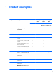
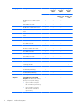
1 Product description Category Product Name Description Compaq Presario CQ42 Compaq Presario CQ42 Compaq Presario CQ42 UMA Discrete UMA Models 150 – 199 UMA Models 100 – 149 √ √ √ Compaq Presario CQ42 Notebook PC HP G42 Notebook PC Processors HP G42 √ Intel® Arrandale™ i7-620M, 2.66-GHz, SC turbo, 4-MB L3 cache √ √ √ i5-540M, 2.53-GHz, SC turbo, 3-MB L3 cache √ √ √ i5-520M, 2.4-GHz, SC turbo, 3-MB L3 cache √ √ √ i5-430M 2.26-GHz (turbo to 2.
Category Description HP G42 Compaq Presario CQ42 Compaq Presario CQ42 Compaq Presario CQ42 UMA Discrete UMA Models 150 – 199 UMA Models 100 – 149 DC N830 Tri-core 2.1Ghz 1.5M L2 35W √ √ √ N620 DDR3-1333 Mhz √ √ √ DC QC P920 1.6Ghz 2M L2 25W √ √ √ DC P820 Tri-Core 1.8Ghz 1.5M L2 25W √ √ √ DC P820 Tri-Core 1.8Ghz 1.5M L2 25W √ √ √ DC N530 DC 2.5GHz L2 35W √ √ √ P520 DDR3-1066 Mh √ √ √ DC N330 2.
Category Description HP G42 Compaq Presario CQ42 Compaq Presario CQ42 Compaq Presario CQ42 UMA Discrete UMA Models 150 – 199 UMA Models 100 – 149 √ Intel UMA (integrated)/GMA 4500M - GL40 chipset with shared video memory (memory size is dynamic change): ● Up to 1759 MB for computers with more than 4096 MB of system memory (64 bit) ● Up to 1309 MB for computers with more than 4096 MB of system memory (32 bit) ● Up to 1309 MB for computers with more than 3072 MB of system memory ● Up to 797 M
Category Description HP G42 Compaq Presario CQ42 Compaq Presario CQ42 Compaq Presario CQ42 UMA Discrete UMA Models 150 – 199 UMA Models 100 – 149 √ DDR3, 800-MHz, dual-channel memory (DDR3 1333 MHz can be downgraded to DDR3 800 MHz) Supports the following configurations: Hard drives ● 4096 MB (2048 MB × 2) √ √ √ √ ● 3072 MB (1024 MB × 1 + 2048 MB × 1) √ √ √ √ ● 2048 MB (2048 MB × 1) √ √ √ √ ● 2048 MB (1024 MB × 2) √ √ √ √ ● 1024 MB (1024 MB × 1) √ √ √ √ Supports 9.
Category HP G42 Compaq Presario CQ42 Compaq Presario CQ42 Compaq Presario CQ42 UMA Discrete UMA Models 150 – 199 UMA Models 100 – 149 Fixed (no tilt) √ √ √ √ 640 × 480 by 24 frames per second √ √ √ √ Microphone One microphone, analog √ √ √ √ Audio HD audio √ √ √ √ Supports Microsoft Premium requirements √ √ √ √ Altec Lansing speakers √ √ √ √ Modem Support for optional high-speed 56k modem √ √ √ √ Ethernet Integrated 10/100 network interface card (NIC) √ √ √
Category Ports Keyboard/ pointing devices Power requirements Description HP G42 Compaq Presario CQ42 Compaq Presario CQ42 Compaq Presario CQ42 UMA Discrete UMA Models 150 – 199 UMA Models 100 – 149 Single port configured as either HDMI or 5-in-1 Digital Media Slot √ √ √ Supports mini versions of SD, MMC, and MS Duo with adapter (adapter not included) √ √ √ √ VGA (Dsub 15-pin) supporting 1600 x 1200 resolution at 75 Hz; disabled when connected to devices through Expansion port 3 √ √
Category Serviceability Description HP G42 Compaq Presario CQ42 Compaq Presario CQ42 Compaq Presario CQ42 UMA Discrete UMA Models 150 – 199 UMA Models 100 – 149 Windows 7 Home Premium (32 & 64 bit) √ √ √ Windows 7 Home Basic (32 & 64 bit) √ √ Windows 7 Starter (32 bit) √ √ Free DOS √ √ Novell Linux √ √ √ End-user replaceable parts: AC adapter √ √ √ √ Battery (system) √ √ √ √ Hard drive √ √ √ √ Memory module √ √ √ √ Optical drive √ √ √ √ Mini-card device
2 External component identification Identifying the hardware Components included with the computer may vary by region and model. The illustrations in this chapter identify the standard features on most computer models. To see a list of hardware installed in the computer, follow these steps: 1. Select Start > My Computer. 2. In the left pane of the System Tasks window, select View system information. 3. Select Hardware tab > Device Manager.
Top components TouchPad Component (1) Description TouchPad off indicator To switch the TouchPad zone on and off, quickly double-tap the TouchPad off indicator. NOTE: When the TouchPad zone is active, the light is off. (2) TouchPad zone Moves the pointer and selects or activates items on the screen. (3) Left TouchPad button Functions like the left button on an external mouse. (4) Right TouchPad button Functions like the right button on an external mouse.
Lights Component (1) TouchPad light ● On: The TouchPad is disabled. ● Off: The TouchPad is enabled. (2) Caps lock light On: Caps lock is on. (3) Power light ● On: The computer is on. ● Blinking: The computer is in the Sleep state. ● Off: The computer is off or in Hibernation. ● White: An integrated wireless device, such as a wireless local area network (WLAN) device and/or a Bluetooth® device, is on. ● Amber: All wireless devices are off.
Button and speakers Component Description (1) Speakers (2) Produce sound. (2) Power button ● When the computer is off, press the button to turn on the computer. ● When the computer is on, press the button briefly to initiate Sleep. ● When the computer is in the Sleep state, briefly press the button to exit Sleep. ● When the computer is in Hibernation, briefly press the button to exit Hibernation.
Keys 12 Component Description (1) esc key Displays system information when pressed in combination with the fn key. (2) fn key Displays system information when pressed in combination with the esc key. (3) Windows logo key Displays the Windows Start menu. (4) Windows applications key Displays a shortcut menu for items beneath the pointer. (5) Navigation keys Navigate using the Up, Down, Left and Right arrow keys. (6) Action keys Execute frequently used system actions.
Display Component Description (1) Internal microphone Records sound. (2) Integrated webcam (select models only) Records audio and video and captures still photographs. (3) Integrated webcam light (select models only) On: The integrated webcam is in use.
Right-side components Component Description (1) Optical drive Reads and writes to optical discs. (2) Optical drive light Blinking: The optical drive is being accessed. (3) USB port Connects an optional USB device. (4) RJ-11 (modem) jack (select models only) Connects a modem cable. (5) AC adapter/power/battery light ● White: The computer is connected to external power and the battery is fully charged. ● Blinking white: The computer is in the Sleep state. ● Amber: A battery is charging.
Left-side components Component Description (1) External monitor port Connects an external VGA monitor or projector. (2) Vent Enables airflow to cool internal components. NOTE: The computer fan starts up automatically to cool internal components and prevent overheating. It is normal for the internal fan to cycle on and off during routine operation.
Bottom components Component Description (1) Battery bay Holds the battery. (2) Battery release latch Releases the battery from the battery bay. (3) Vents (4) Enable airflow to cool internal components. NOTE: The computer fan starts up automatically to cool internal components and prevent overheating. It is normal for the internal fan to cycle on and off during routine operation. (4) Memory module compartment Contains 2 memory module slots and, on select models, the wireless LAN (WLAN) device.
Wireless antennas At least 2 antennas send and receive signals from one or more wireless devices. These antennas are not visible from the outside of the computer. NOTE: For optimal transmission, keep the areas immediately around the antennas free from obstructions. To see wireless regulatory notices, refer to the section of the Regulatory, Safety and Environmental Notices that applies to your country or region. These notices are located in Help and Support.
Additional hardware components Component Description (1) Power cord* Connects an AC adapter to an AC outlet. (2) AC adapter Converts AC power to DC power. (3) Battery* Powers the computer when the computer is not plugged into external power. *Power cords vary in appearance by country or region. WARNING! Connecting the internal analog modem to a digital line can permanently damage the modem. Immediately disconnect the modem cable if you accidentally connect it to a digital line.
3 Illustrated parts catalog Serial number location When ordering parts or requesting information, provide the computer serial number and model number located in the battery bay of the computer.
Computer major components Item Description (1) 35.6 cm (14-in), WXGA, BrightView display assembly Spare part number NOTE: See Display assembly components on page 27 for more display assembly internal component spare part information.
Item (2) (3) Description Spare part number ● For use with integrated microphone and webcam; Presario, biscotti 597617-001 ● For use with integrated microphone and webcam; HP, biscotti 600163-001 ● For use with integrated microphone and webcam; HP, silver 606155-001 ● For use with integrated microphone and webcam; HP, white 606156-001 Keyboards ● For use in Brazil 600175-201 ● For use in English and French Canada 600175-121 ● For use in Latin America 600175-161 ● For use in South K
Item (9) Description Spare part number For use in models with discrete graphics subsystem 615577–001 For use in models with discrete graphics subsystem 615578–001 ● For use in models with Unified Memory Architecture (UMA) graphics subsystem 595182-001 ● For use in models with discrete graphics subsystem and HDMI card reader 595183-001 ● For use in models with UMA graphics subsystem and HDMI card reader 595184-001 ● For use in models with UMA graphics subsystem memory, Intel® GL40 chipset,
Item Description Spare part number ● 580101-002 Afghanistan, Albania, Algeria, Andorra, Angola, Antigua and Barbuda, Argentian, Armenia, Australia, Austria, Azerbaijan, Bahamas, Bahrain, Barbados, Belgium, Belize, Benin, Bhutan, Bosnia and Herzegovina, Botswana, Brazil, Brunei, Bulgeria, Burkina Faso, Burundi, Cambodia, Cameroon, Cape Verde, Central African Republic, Chad, Chile, China, Colombia, Comoros, Congo, Costa Rica, Croatia, Cyprus, Czech Republic, Zaire, Denmark, Djibouti, Dominica, Dominican
Item (14) 24 Description Spare part number ● 582562-002 For use in Afghanistan, Albania, Algeria, Andorra, Angola, Antigua and Barbuda, Argentina, Armenia, Aruba, Australia, Austria, Azerbaijan, The Bahamas, Bahrain, Bangladesh, Barbados, Belgium, Belize, Benin, Bermuda, Bhutan, Bolivia, Bosnia and Herzegovina, Botswana, Brazil, The British Virgin Islands, Brunei, Bulgaria, Burkina Faso, Burundi, Cameroon, Cape Verde, the Central African Republic, Chad, Chile, China, Colombia, Comoros, Congo, Costa,
Item Description Spare part number ● Intel Core 2 Duo Mobile,T4300, 2.1-GHz 572929-001 ● Intel Core 2 Duo Mobile processor T3100 - 1.9-GHz 572925-001 ● Intel Core 2 Duo Mobile processor T3300 2.0-GHz 592399-001 ● Intel Core 2 Duo Mobile processor T4500 2.
Item 26 Description Spare part number ● 320-GB 7200 RPM 600169-001 ● 250-GB 7200 RPM 575598-001 ● 160-GB 7200 RPM 600167-001 (22) Hard drive cable/adapter (included with the cable kit; see Mass storage devices on page 30) 610791–001 (23) Optical drive cable (included in the cable kit) 610791-001 (24) Optical drives (12.
Display assembly components Item Description (1) Display bezel Spare part number ● HP, for use with microphone and webcam 592147-001 ● Presario, for use with microphone and webcam 592148-001 (2) 35.
Item Description Spare part number Display cable (shown with display panel) (4) Webcam cable (5) Antennas and cables (6) (7) 28 Display back cover ● Presario, matte black 592149-001 ● Presario, biscotti 600164-001 ● HP, biscotti 600165-001 ● HP, silver 606157-001 ● HP, white 606158-001 Webcam module 600166-001 Display screw kit (not illustrated; includes screws and screw covers) 592152-001 Display rubber display kit (not illustrated) 595198-001 Chapter 3 Illustrated parts catalog
Plastics Kit Item Description Spare part number Plastics kit 600190-001 (1) Hard drive bay cover (includes captive screws) (2) Wireless/memory module mini-card compartment cover (includes captive screw) Plastics Kit 29
Mass storage devices Item Description (1) Hard drive (include hard drive bracket) (2) 30 Spare part number ● 640–GB 5400 RPM 615808-001 ● 500-GB 7200 RPM 600170-001 ● 320-GB 7200 RPM 600169-001 ● 250-GB 7200 RPM 575598-001 ● 160-GB 7200 RPM 600167-001 Hard drive hardware kit (contains screws, hard drive bracket, not illustrated) 600191-001 Hard drive cable/adapter (included in the cable kit) 610791–001 Optical drives (12.
Miscellaneous parts Description Spare part number AC adapters ● 90-W Smart AC adapter with power factor correction (PFC) 613152-001 ● 90-W AC adapter with power factor correction (PFC) 613160-001 ● 65-W AC Smart, slim, AC adapter 613153-001 ● 65-W Smart power adapter with power factor correction (PFC) for use in India 613161-001 Power cord, AC, 3 wire, black, 1.
Sequential part number listing 32 Spare part number Description 490371-001 Power cord, AC, 3-pin, black, 1.83-m, for use in North America 490371-011 Power cord, AC, 3-pin, black, 1.83-m, for use in Australia 490371-031 Power cord, AC, 3-pin, black, 1.83-m, for use in the United Kingdom and Singapore 490371-061 Power cord, AC, 3-pin, black, 1.83-m, for use in Italy 490371-201 Power cord, AC, 3-pin, black, 1.83-m, for use in Thailand 490371-202 Power cord, AC, 3-pin, black, 1.
Spare part number Description 580101-002 Atheros AR9285 802.
34 Spare part number Description 592147-001 Display bezel, HP, for use with microphone and webcam 592148-001 Display bezel, Presario, for use with microphone and webcam 592149-001 Display back cover, Presario, matte black 592150-001 Display hinge cover 592151-001 Display cable kit 592152-001 Display screw kit (not illustrated) 592399-001 Processor, Intel Core 2 Duo Mobile processor T3300 2.
Spare part number Description 594172-001 Processor Advanced Micro Devices (AMD) DC N530 DC 2.
36 Spare part number Description 600177-001 Base enclosure (with modem cable and ODD cable) for use with HDMI card reader and without modem module, biscotti 600178-001 Base enclosure (with modem cable and ODD cable) for use without HDMI card reader and with modem module, biscotti 600179-001 Base enclosure (with modem cable and ODD cable) for use with HDMI card reader without modem, matte black 600180-001 Base enclosure (with modem cable and ODD cable) for use without HDMI card reader and with mode
Spare part number Description 606609-001 Thermal module (includes fan and heat sink) for use in models that use UMA graphics subsystem memory 606610-001 Thermal module (includes fan and heat sink) for use in models that use discrete graphics subsystem memory 608119-001 Optical drive, DVD±RW SuperMulti DL Drive with LightScribe, silver 608120-001 Optical drive, DVD±RW SuperMulti DL Drive with LightScribe, white 608121-001 Optical drive, Blu-ray Disc ROM LightScribe with SuperMulti DVD±R/RW Double-
4 Removal and replacement procedures Preliminary replacement requirements Tools required You will need the following tools to complete the removal and replacement procedures: ● Flat-bladed screwdriver ● Magnetic screwdriver ● Phillips P0 and P1 screwdrivers Service considerations The following sections include some of the considerations that you must keep in mind during disassembly and assembly procedures.
Cables and connectors CAUTION: When servicing the computer, be sure that cables are placed in their proper locations during the reassembly process. Improper cable placement can damage the computer. Cables must be handled with extreme care to avoid damage. Apply only the tension required to unseat or seat the cables during removal and insertion. Handle cables by the connector whenever possible. In all cases, avoid bending, twisting, or tearing cables.
Grounding guidelines Electrostatic discharge damage Electronic components are sensitive to electrostatic discharge (ESD). Circuitry design and structure determine the degree of sensitivity. Networks built into many integrated circuits provide some protection, but in many cases, ESD contains enough power to alter device parameters or melt silicon junctions. A discharge of static electricity from a finger or other conductor can destroy static-sensitive devices or microcircuitry.
Packaging and transporting guidelines Follow these grounding guidelines when packaging and transporting equipment: ● To avoid hand contact, transport products in static-safe tubes, bags, or boxes. ● Protect ESD-sensitive parts and assemblies with conductive or approved containers or packaging. ● Keep ESD-sensitive parts in their containers until the parts arrive at static-free workstations. ● Place items on a grounded surface before removing items from their containers.
Equipment guidelines Grounding equipment must include either a wrist strap or a foot strap at a grounded workstation. ● When seated, wear a wrist strap connected to a grounded system. Wrist straps are flexible straps with a minimum of one megohm ±10% resistance in the ground cords. To provide proper ground, wear a strap snugly against the skin at all times. On grounded mats with banana-plug connectors, use alligator clips to connect a wrist strap.
Component replacement procedures This chapter provides removal and replacement procedures. There are as many as 75 screws, in 12 different sizes, that must be removed, replaced, or loosened when servicing the computer. Make special note of each screw size and location during removal and replacement. Serial number The serial number label, located in the battery bay of the computer, provides important information that you may need when contacting technical support.
Computer feet Description Spare part number Rubber Feet Kit 600184-001 The computer feet are adhesive-backed rubber pads. The feet attach to the base enclosure in the locations illustrated below.
Battery Description Spare part number 6-cell 55-WH (2.55Ah) LI-ion 593554-001 6-cell 47-WH (2.2-Ah) LI-ion 593553-001 Before disassembling the computer, follow these steps: 1. Shut down the computer. If you are unsure whether the computer is off or in Hibernation, turn the computer on, and then shut it down through the operating system. 2. Disconnect all external devices connected to the computer. 3.
Hard drive NOTE: All hard drive spare part kits include a hard drive bracket. Description Spare part number 640-GB 5400 RPM 615808-001 500-GB 7200 RPM 600170-001 320-GB 7200 RPM 600169-001 250-GB 7200 RPM 575598-001 160-GB 7200 RPM 600167-001 Hard drive hardware kit (includes screws and hard drive bracket) 600191-001 Hard drive cable/adaptor (included in the cable kit) 610791–001 Before removing the hard drive, follow these steps: 1. Shut down the computer.
3. Lift the left side of the hard drive cover (2), swing it forward, and remove the cover (3). The hard drive cover is included in the plastics kit, spare part number 600190-001. 4. Remove the three Phillips PM2.5×4.0 screws (1) that secure the hard drive to the computer. 5. Use the hard drive bracket to lift the hard drive out (2) of the hard drive compartment.
6. Disconnect the hard drive cable from the system board. 7. Remove the hard drive. 8. If it is necessary to replace the hard drive bracket, remove the four Phillips PM3.0×3.0 screws (1) that secure the hard drive bracket to the hard drive 9. Lift the bracket (2) straight up. Reverse this procedure to install the hard drive.
Optical drive Description Spare part number DVD±RW SuperMulti DL Drive with LightScribe, matte black 600171-001 DVD±RW SuperMulti DL Drive with LightScribe, biscotti 600172-001 DVD±RW SuperMulti DL Drive with LightScribe, silver 608119-001 DVD±RW SuperMulti DL Drive with LightScribe, white 608120-001 Blu-ray Disc ROM LightScribe with SuperMulti DVD±R/RW Double-Layer, matte black 600173-001 Blu-ray Disc ROM LightScribe with SuperMulti DVD±R/RW Double-Layer, biscotti 600174-001 Blu-ray Disc ROM
4. Remove the optical drive (3). 5. If it is necessary to replace the optical drive bracket, position the optical drive with the optical drive bracket toward you. 6. Remove the two Phillips PM2.0×3.0 screws (1) that secure the optical drive bracket to the optical drive. 7. Remove the optical drive bracket (2). Reverse the above procedure to reassemble and install the optical drive.
WLAN module Description Spare part number Atheros AR9285 802.11 a/b/g/n 2x2 WiFi adapter for use in Canada, the Cayman Islands, Guam, Puerto Rico, the United States, and the US Virgin Islands 580101-001 Atheros AR9285 802.
Description Spare part number SPS-WLAN BGN + BT HMC Combo Matador 600370-001 SPS-WLAN 802.11 bgn Shiraz HMC 593836-001 SPS-WLAN BGN (1x1) + BT HMC Combo Rashi 602992-001 Before removing the WLAN module, follow these steps: 1. Shut down the computer. If you are unsure whether the computer is off or in Hibernation, turn the computer on, and then shut it down through the operating system. 2. Disconnect all external devices connected to the computer. 3.
6. Remove the WLAN module (3) by pulling it away from the slot at an angle. CAUTION: To prevent an unresponsive system, replace the wireless module only with a wireless module authorized for use in the computer by the governmental agency that regulates wireless devices in your country or region. If you replace the module and then receive a warning message, remove the module to restore computer functionality, and then contact technical support through Help and Support.
Memory module Description Spare part number 2048-MB, PC3 10600, 1333-MHz 598856-001 1024-MB, PC3 10600, 1333-MHz 598859-001 Before removing the memory module, follow these steps: 1. Shut down the computer. If you are unsure whether the computer is off or in Hibernation, turn the computer on, and then shut it down through the operating system. 2. Disconnect all external devices connected to the computer. 3.
3. Lift cover off the computer. The mini-card compartment cover is included in the plastics kit, spare part number 600190-001. NOTE: Small tabs hold the cover in place. Firmly pull up on the cover to release the tabs. 4. Spread the retaining tabs (1) on each side of the memory module slot to release the memory module. (The edge of the module opposite the slot rises away from the computer.) 5. Remove the module (2) by pulling it away from the slot at an angle.
Keyboard Description Spare part number Keyboard for use in Brazil 600175-201 Keyboard for use in English and French Canada 600175-121 Keyboard for use in for use in Latin America 600175-161 Keyboard for use in South Korea 600175-AD1 Keyboard for use in Taiwan 600175-AB1 Keyboard for use in Thailand 600175-281 Keyboard for use in the United States 600175-001 Before removing the keyboard, follow these steps: 1. Shut down the computer.
3. Turn the computer display-side up with the front toward you. 4. Open the computer as far as possible. 5. Release the top edge of the keyboard by lifting it up to disengage the keyboard from the tabs on the top cover (1). 6. Slide the top edge of the keyboard back (2) until it rests against the display. 7. Release the zero insertion force (ZIF) connector (1) to which the keyboard cable is attached and disconnect the keyboard cable (2) from the system board. 8. Remove the keyboard.
Top cover Description Spare part number Top cover (includes Touchpad and bracket, button board, and cable), matte black 600181-001 Top cover, bicotti 600182-001 Top cover, silver 606161-001 Top cover, white 606162-001 Before removing the switch cover, follow these steps: 1. Shut down the computer. If you are unsure whether the computer is off or in Hibernation, turn the computer on, and then shut it down through the operating system. 2. Disconnect all external devices connected to the computer.
3. Remove the five Phillips PM2.5×6.5 screws (2), the two Phillips PM2.5x4.0 screws (3), and the four Phillips PM2.5x3.0 screws (4) that secure the top cover to the base enclosure. 4. Turn the computer display-side up with the front toward you. 5. Open the computer as far as possible. 6. Release the ZIF connector to which the touchpad (1) is connected and disconnect the cable from the system board. 7.
9. Release the ZIF connector to which the power button board cable (4) is connector and disconnect the cable from the system board. 10. Remove the Phillips PM2.5×6.5 screw (1) from the top cover, disengage the rear edge of the top cover (2) from the base enclosure, and then remove the cover from the computer (3). Reverse this procedure to install the switch cover.
Speaker assembly Description Spare part number Speaker assembly 600189-001 Before removing the speaker assembly, follow these steps: 1. Shut down the computer. If you are unsure whether the computer is off or in Hibernation, turn the computer on, and then shut it down through the operating system. 2. Disconnect all external devices connected to the computer. 3.
Power button board Description Spare part number Power button board (with cable) 600188-001 Before removing the power button board, follow these steps: 1. Shut down the computer. If you are unsure whether the computer is off or in Hibernation, turn the computer on, and then shut it down through the operating system. 2. Disconnect all external devices connected to the computer. 3.
TouchPad button board Description Spare part number TouchPad button board 604603-001 Before removing the TouchPad button board, follow these steps: 1. Shut down the computer. If you are unsure whether the computer is off or in Hibernation, turn the computer on, and then shut it down through the operating system. 2. Disconnect all external devices connected to the computer. 3.
Reverse the above procedure to reassemble and install the TouchPad button board.
Modem module Description Spare part number High-speed 56K modem for use in all countries and regions except Australia and New Zealand 510100-001 High-speed 56K modem for use in Australia and New Zealand 510100-011 Modem module cable with RJ-11 connector (included in the cable kit) 610791-001 Before removing the modem module, follow these steps: 1. Shut down the computer.
4. Lift up on the front of the modem module (3) to disconnect it from the system board. 5. Remove the modem module. Reverse the above procedure to install the modem module, and be sure that the connector on the bottom of the modem module connects firmly into the system board.
Bluetooth module Description Spare part number Bluetooth module 537921-001 Bluetooth module cable 602822-001 Before removing the Bluetooth module, follow these steps: 1. Shut down the computer. If you are unsure whether the computer is off or in Hibernation, turn the computer on, and then shut it down through the operating system. 2. Disconnect all external devices connected to the computer. 3.
Reverse the above procedure to install the Bluetooth module.
USB board Description Spare part number USB board (includes cable) 600631-001 Before removing the USB board, follow these steps: 1. Shut down the computer. If you are unsure whether the computer is off or in Hibernation, turn the computer on, and then shut it down through the operating system. 2. Disconnect all external devices connected to the computer. 3.
Reverse this procedure to install the USB board.
Power connector cable Description Spare part number Power connector cable (includes cable and connector) 600630-001 Before removing the power connector cable, follow these steps: 1. Shut down the computer. If you are unsure whether the computer is off or in Hibernation, turn the computer on, and then shut it down through the operating system. 2. Disconnect all external devices connected to the computer. 3.
Reverse this procedure to install the power connector cable.
Display assembly Description Spare part number 35.6 cm (14-in) WXGA Brightview display assembly for use with integrated microphone and webcam; Presario, matte black 592146-001 35.6 cm (14-in) WXGA Brightview display assembly for use with integrated microphone and webcam; Presario, biscotti 597617-001 35.6 cm (14-in) WXGA Brightview display assembly for use with integrated microphone and webcam; HP, biscotti 600163-001 35.
6. Disconnect the webcam cable (2) from the system board. CAUTION: Support the display assembly when removing the display screws in the following steps. Failure to support the display assembly can result in damage to the assembly and other components. 74 7. Remove the four black Phillips PM2.5×6.5 screws (1) that secure the display assembly to the computer. 8. Remove the display assembly (2).
9. If it is necessary to replace any of the display assembly internal components, remove the following screw covers and screws. The display screw covers are included in the display screw kit, spare part number 592152-001. (1) Two Mylar screw covers on the display bezel bottom edge (2) Two Phillips PM2.5×4.0 screws 10. Flex the inside edge of the top (1), the left and right sides (2), and the bottom (3) of the display bezel until the bezel disengages from the display back cover. 11.
12. If it is necessary to replace the webcam module, disconnect the webcam cable (1) from the module. Lift the webcam from the double-sided tape on the display back cover, and remove the webcam. 13. If it is necessary to replace the display panel, remove the eight Phillips PM2.5×5.0 screws (1) that secure the display panel to the display enclosure, and then lift the panel from the enclosure (2). The display panel is available using the spare part number 592144-001. 14.
The display cable is available in the display cable kit, spare part number 592151-001. 15. If it is necessary to replace the display bracket and hinges, remove the Phillips PM2.0×3.0 screws (1) that secure each bracket to the display. 16. Remove the display hinges (2) from the display. The display bracket and hinge set is available using spare part number 600627-001. 17.
20. Remove the wireless antennas and cables (4) from the display enclosure. The wireless antennas and cables are included in the display cable kit, spare part number 592151-001. 21. If it is necessary to remove the webcam cable, remove the cable from the adhesive strips (1) along the cable path on the display back cover, and then remove the webcam cable (2).
22. If it is necessary to remove the microphone, release the microphone cable from the adhesive strips (1) along the cable path on the display back cover, remove the microphone from the clips on the display back cover (2), and then remove the microphone and microphone cable (3). The microphone and cable is included in the display cable kit, spare part number 592151-001, Reverse this procedure to reassemble and install the display assembly.
System board Description Spare part number System board for use in models with discrete graphics subsystem 595181-001 System board for use in models with Unified Memory Architecture (UMA) graphics subsystem 595182-001 System board for use in models with discrete graphics subsystem and HDMI card reader 595183-001 System board for use in models with UMA graphics subsystem and HDMI card reader 595184-001 System board for use in models with UMA graphics subsystem memory, Intel® GL40 chipset, and HDMI
4. Remove the battery (see Battery on page 45). 5. Remove the following components: a. Hard drive (see Hard drive on page 46) b. WLAN (see WLAN module on page 51) c. Optical drive (see Optical drive on page 49) d. Keyboard (see Keyboard on page 56) e. Top cover (see Top cover on page 58) f. Speaker assembly (see Speaker assembly on page 61) g. Display assembly (see Display assembly on page 73) h.
5. Release the system board by sliding it to the right at an angle (3) until the connectors on the left side of the system board clear the base enclosure, and then remove the system board. 6. If it is necessary to replace the modem module cable, remove the RJ-11 connector (1) from the clip built into the base enclosure. 7. Remove the modem module cable (2) from the routing channel built into the base enclosure. The modem module cable is available using spare part number 610791-001.
Optical drive SATA cable and connector Description Spare part number Optical drive cable (included in the cable kit) 610791-001 Before removing the optical drive cable, follow these steps: 1. Shut down the computer. If you are unsure whether the computer is off or in Hibernation, turn the computer on, and then shut it down through the operating system. 2. Disconnect all external devices connected to the computer. 3.
2. 84 Release the cable from the clips on the base enclosure (2), and then remove the cable (3).
RTC battery Description Spare part number RTC battery 602745-001 Before removing the RTC battery, follow these steps: 1. Shut down the computer. If you are unsure whether the computer is off or in Hibernation, turn the computer on, and then shut it down through the operating system. 2. Disconnect all external devices connected to the computer. 3. Disconnect the power from the computer by first unplugging the power cord from the AC outlet and then unplugging the AC adapter from the computer. 4.
3. Remove the RTC battery (2). Reverse this procedure to install the RTC battery.
Fan/heat sink assembly Description Spare part number Fan/heat sink assembly for use in models that use Universal Memory Architecture (UMA) graphics subsystem memory (includes thermal replacement material) 595832-001 Fan/heat sink assembly for use in models that use discrete graphics subsystem memory (includes thermal material) 595833–001 Fan/heat sink assembly for use in models that use and UMA graphics subsystem memory and the Intel® GL40 chipset (includes thermal material) 606573-001 Fan/heat sink
Remove the fan/heat assembly (fan/heat sink appearance may vary): 1. Turn the system board upside down. 2. Disconnect the fan cable (1) from the system board. 3. Follow the sequence embossed on heat sink to loosen the four Phillips PM2.5×7.0 captive screws (2) that secure the fan/heat sink assembly to the system board.
The thermal material must be thoroughly cleaned from the surface of the fan/heat sink assembly (1) and (3), and the processor component (2), each time the fan/heat sink assembly is removed. Thermal pads and thermal paste must be installed on all surfaces before the fan/heat sink assembly is reinstalled. The following illustration shows the locations for thermal material on systems with UMA graphics subsystems. Reverse this procedure to install the fan/heat sink assembly.
Processor NOTE: All processor spare part kits include thermal material. 90 Description Spare part number Intel Arrandale Core 620M 2.26-GHz 587259-001 Intel Arrandale 540M 2.53-GHz 594188-001 Intel Arrandale 520M 2.4-GHz 594187-001 Intel Arrandale i5-430M 2.26-GHz 597624-001 Intel Arrandale i3-350M 2.26-GHz 597623-001 Intel Arrandale 370M, 2.4 GHz 613586–001 Intel Arrandale i5-450M 2.4GHz 613585–001 Intel Arrandale 3-370M 2.4GHz 613584–001 Intel Celeron 900,2.
Before removing the processor, follow these steps: 1. Shut down the computer. If you are unsure whether the computer is off or in Hibernation, turn the computer on, and then shut it down through the operating system. 2. Disconnect all external devices connected to the computer. 3. Disconnect the power from the computer by first unplugging the power cord from the AC outlet and then unplugging the AC adapter from the computer. 4. Remove the battery (see Battery on page 45). 5.
2. Lift the processor (2) straight up and remove it. NOTE: The gold triangle (3) on the processor must be aligned with the triangle icon (4) embossed on the processor socket when you install the processor. Reverse this procedure to install the processor.
5 Setup Utility Computer Setup in Windows 7 To view the drives installed on the computer, select Start > Computer. On models with a secondary hard drive (drive D), the optical drive becomes drive E. The next drive added to the system, such as a new USB drive, will be assigned the next available drive letter. Starting Setup Utility Setup Utility is a ROM-based information and customization utility that can be used even when your Windows® operating system is not working.
Using Setup Utility Changing the language of Setup Utility The following procedure explains how to change the language of Setup Utility. If Setup Utility is not already running, begin at step 1. If Setup Utility is already running, begin at step 2. 1. Open Setup Utility by turning on or restarting the computer. While the “Press the ESC key for Startup Menu” message is displayed in the lower-left corner of the screen, press f10. – or – Open Setup Utility by turning on or restarting the computer.
Displaying system information The following procedure explains how to display system information in Setup Utility. If Setup Utility is not open, begin at step 1. If Setup Utility is open, begin at step 2. 1. Open Setup Utility by turning on or restarting the computer. While the “Press the ESC key for Startup Menu” message is displayed in the lower-left corner of the screen, press f10. – or – Open Setup Utility by turning on or restarting the computer.
Exiting Setup Utility You can exit Setup Utility with or without saving changes. ● To exit Setup Utility and save your changes from the current session: If the Setup Utility menus are not visible, press esc to return to the menu display. Then use the arrow keys to select Exit > Exit Saving Changes, and then press enter. ● To exit Setup Utility without saving your changes from the current session: If the Setup Utility menus are not visible, press esc to return to the menu display.
System Configuration menu Select To do this Language Support Change the language of Setup Utility. Button Sound (select models only) Enable/disable the capacitive button tapping sound. Virtualization Technology (select models only) Enable/disable the processor Virtualization Technology. Processor C6 State (select models only) Enable/disable the processor C6 sleep state. LAN Power Saving (select models only) Enable/disable LAN Power Saving.
98 Select To do this Secondary Hard Disk Self Test (select models only) Run a comprehensive self-test on a secondary hard drive. Memory Test Run a diagnostic test on the system memory.
Computer Setup in Linux Starting Computer Setup Computer Setup is a preinstalled, ROM-based utility that can be used even when the operating system is not working or will not load. NOTE: Some of the Computer Setup menu items listed in this guide may not be supported by your computer. NOTE: Pointing devices are not supported in Computer Setup. You must use the keyboard to navigate and make selections.
Your preferences go into effect when the computer restarts. Restoring factory settings in Computer Setup To return all settings in Computer Setup to the values that were set at the factory, follow these steps: 1. Open Computer Setup by turning on or restarting the computer, and then pressing f10 while the "F10 = ROM Based Setup" message is displayed in the lower-left corner of the screen. 2. Use the arrow keys to select File > Restore Defaults, and then press enter. 3.
Computer Setup menus The menu tables in this section provide an overview of Computer Setup options. NOTE: Some of the Computer Setup menu items listed in this chapter may not be supported by your computer. File menu Select To do this System information ● View identification information for the computer. ● View specification information for the processor, cache and memory size, and system ROM. Restore Defaults Replace the configuration settings in Computer Setup with the original factory settings.
Security menu NOTE: Some of the menu items listed in this section may not be supported by your computer. Select To do this Setup Password Enter, change, or delete a setup password. Power-On Password Enter, change, or delete a power-on password. Password Options ● Enable/disable stringent security. ● Enable/disable the password requirement on computer restart. ● Enable/disable DriveLock on any computer hard drive. ● Enter, change, or disable DriveLock on an optional MultiBay hard drive.
System Configuration menu NOTE: Some of the listed System Configuration options may not be supported by your computer. Select To do this Language Change the Computer Setup language. Boot options ● Set an f9, f10, and f12 delay when starting up. ● Enable/disable CD-ROM boot. ● Enable/disable floppy boot. ● Enable/disable internal network adapter boot. ● Enable/disable MultiBoot, which sets a boot order that can include most boot devices in the system.
Select To do this Built-in device options ● Enable/disable embedded WLAN Device Radio. ● Enable/disable embedded Bluetooth Device Radio. ● Enable/disable Network Interface Controller (NIC) ● Enable/disable LAN/WLAN Switching. ● Enable/disable Wake on LAN. ● Enable/disable the integrated camera (webcam) ● Enable/disable USB port. ● Enable/disable ExpressCard slot.
6 Specifications Computer specifications Dimensions Depth 22.8 cm (8.98 in) Width 34.2 cm (13.46 in) Height (front to rear) 31.5 to 36.5 cm (1.24 to 1.44 in) Weight (lowest weight configuration) < 2.20 kg (4.85 lbs) Input power Operating voltage 18.5 V dc @ 4.74 A – 90 W Operating current 4.
35.6-cm (14.0-in) display specifications Dimensions Height 17.6 cm (17.6 cm) Width 31.1 cm (12.24 in) Diagonal 35.7 cm (14.06 in) Number of colors Up to 16.8 million Contrast ratio 300:1 (typical) Brightness 200 nits (typical) Pixel resolution Pitch 0.259 × 0.259 mm Format 1280 × 800; HD: 1366 × 768 Configuration RGB vertical stripe Backlight LED Character display 80 × 25 Total power consumption 4.
Hard drive specifications 500-GB* 320-GB* 250-GB* 160-GB* Height 9.5 mm 9.5 mm 9.5 mm 9.5 mm Width 70 mm 70 mm 70 mm 70 mm Weight 101 g 101 g 101 g 101 g Interface type SATA SATA SATA SATA Transfer rate 100 MB/sec 100 MB/sec 100 MB/sec 100 MB/sec Security ATA security ATA security ATA security ATA security Single track 1.0 ms 1.5 ms 2.0 ms 1.5 ms Average 14.0 ms 12.0 ms 12.0 ms 11.0 ms Maximum 22.0 ms 22.0 ms 22.0 ms 22.
DVD±RW SuperMulti Double-Layer Drive with LightScribe specifications Applicable disc Read CD-DA, CD+(E)G, CD-MIDI, CD-TEXT, CD-ROM, CD-ROM XA, MIXED MODE CD, CD-I, CD-I Bridge (Photo-CD, Video CD), Multisession CD (PhotoCD, CD-EXTRA, Portfolio, CD-R, CD-RW), CD-R, CD-RW, DVD-ROM (DVD-5, DVD-9, DVD-10, DVD-18), DVD-R, DVD-RW, DVD+R, DVD+RW, DVD-RAM Write CD-R and CD-RW, DVD+R, DVD+RW, DVD-R, DVD-RW, DVD-RAM Random access time DVD < 230 ms CD < 175 ms Cache buffer 2 MB Data transfer rate 24X CD-ROM
Blu-ray ROM with LightScribe DVD±R/RW SuperMulti DL Drive specifications Applicable disc Read BD-ROM, BD-ROM-DL, BD-R, BD-R-DL, BD-RE, BD-RE-DL, DVD-ROM, DVD+R, DVD+R-DL, DVD+RW, DVD-R, DVD-R-DL, DVD-RW, DVD-RAM (Ver.2), CDDA, CD-ROM (mode 1 and mode 2), CD-ROM XA (mode 2, form 1 and form 2), Photo CD (single and multiple sessions), CD Extra, CD-R, CD-RW, and CD-TEXT Write DVD-RAM (Ver.
System resource specifications You can use Device Manager to get a graphical view of the system resources that control how the devices work on the computer. System resources you can access from Device Manager are direct memory access (DMA) channels, input/output (I/O) ports, interrupt request (IRQ) lines, and memory addresses. If two devices require the same resource and create a device conflict, you can manually change the resource settings in Device Manager to be sure each setting is unique.
7 Backup and recovery Recovery after a system failure is as complete as your most current backup. HP recommends that you create recovery discs immediately after software setup. As you add new software and data files, you should continue to back up your system on a regular basis to maintain a reasonably current backup.
Depending on your computer model, you may have one of the following backup and recovery solutions: ● Roxio BackOnTrack ● HP Recovery Manager NOTE: For detailed information, perform a search for these topics in Help and Support. Creating recovery discs HP recommends that you create recovery discs to be sure that you can restore your system to its original factory state if you experience serious system failure or instability. Create these discs after setting up the computer for the first time.
Backing up your information As you add new software and data files, you should back up your system on a regular basis to maintain a reasonably current backup. Back up your system at the following times: ● At regularly scheduled times NOTE: Set reminders to back up your information periodically.
Using Windows Backup and Restore To create a backup using Windows Backup and Restore, follow these steps: NOTE: Be sure that the computer is connected to AC power before you start the backup process. NOTE: The backup process may take over an hour, depending on file size and the speed of the computer. 1. Select Start > All Programs > Maintenance > Backup and Restore. 2. Follow the on-screen instructions to set up and create a backup.
Using system restore points When you back up your system, you are creating a system restore point. A system restore point allows you to save and name a snapshot of your hard drive at a specific point in time. You can then recover back to that point if you want to reverse subsequent changes made to your system. NOTE: Recovering to an earlier restore point does not affect data files saved or e-mails created since the last restore point.
Recovery Manager software allows you to repair or restore the system if you experience system failure or instability. Recovery Manager works from recovery discs or from a dedicated recovery partition (select models only) on the hard drive. However, if your computer includes a solid-state drive (SSD), you may not have a recovery partition. If that is the case, recovery discs have been included with your computer. Use these discs to recover your operating system and software.
Linux backup and recovery Use the instructions in this section if SUSE Linux SLED 11 is installed on your computer. To protect your information, back up your files and folders. Then if the system fails, you can restore your important files from copies. You can also use the options listed in this section to restore the operating system and programs that were installed at the factory. CAUTION: Using f11 completely erases hard drive contents and reformats the hard drive.
8 Connector pin assignments Audio-out (headphone) Pin Signal 1 Audio out, left channel 2 Audio out, right channel 3 Ground Audio-in (microphone) Pin Signal 1 Audio signal in 2 Audio signal in 3 Ground 118 Chapter 8 Connector pin assignments
External monitor Pin Signal 1 Red analog 2 Green analog 3 Blue analog 4 Not connected 5 Ground 6 Ground analog 7 Ground analog 8 Ground analog 9 +5 VDC 10 Ground 11 Monitor detect 12 DDC 2B data 13 Horizontal sync 14 Vertical sync 15 DDC 2B clock External monitor 119
RJ-11 (modem) Pin Signal 1 Unused 2 Tip 3 Ring 4 Unused 5 Unused 6 Unused RJ-45 (network) Pin Signal 1 Transmit + 2 Transmit - 3 Receive + 4 Unused 5 Unused 6 Receive - 7 Unused 8 Unused 120 Chapter 8 Connector pin assignments
HDMI Pin Signal 1 TMDS data 2+ 2 TMDS data 2 shield 3 TMDS data 2– 4 TMDS data 1+ 5 TMDS data 1shield 6 TMDS data 1– 7 TMDS data 0+ 8 TMDS data 0 shield 9 TMDS data 0– 10 TMDS clock+ 11 TMDS clock shield 12 TMDS clock– 13 CEC 14 No connect 15 DDC clock 16 DDC data 17 Ground 18 +5V power 19 Hot plug detect 20 Shell HDMI 121
Universal Serial Bus Pin Signal 1 +5 VDC 2 Data - 3 Data + 4 Ground 122 Chapter 8 Connector pin assignments
9 Power cord set requirements The wide range input feature of the computer permits it to operate from any line voltage from 100 to 120 volts AC or from 220 to 240 volts AC. The 3-conductor power cord set included with the computer meets the requirements for use in the country or region where the equipment is purchased. Power cord sets for use in other countries or regions must meet the requirements of the country or region where the computer is used.
Requirements for specific countries or regions Country/region Accredited agency Applicable note number Australia EANSW 1 Austria OVE 1 Belgium CEBC 1 Canada CSA 2 Denmark DEMKO 1 Finland FIMKO 1 France UTE 1 Germany VDE 1 Italy IMQ 1 Japan METI 3 The Netherlands KEMA 1 Norway NEMKO 1 The People's Republic of China CCC 5 South Korea EK 4 Sweden SEMKO 1 Switzerland SEV 1 Taiwan BSMI 4 The United Kingdom BSI 1 The United States UL 2 1.
10 Recycling Battery When a battery has reached the end of its useful life, do not dispose of the battery in general household waste. Follow the local laws and regulations in your area for computer battery disposal. Display WARNING! The backlight contains mercury. Exercise caution when removing and handling the backlight to avoid damaging this component and causing exposure to the mercury. CAUTION: The procedures in this chapter can result in damage to display components.
Perform the following steps to disassemble the display assembly: 1. Remove all screw covers (1) and screws (2) that secure the display bezel to the display assembly. 2. Lift up and out on the left and right inside edges (1) and the top and bottom inside edges (2) of the display bezel until the bezel disengages from the display assembly. 3. Remove the display bezel (3).
4. Disconnect all display panel cables (1) from the display inverter and remove the inverter (2). 5. Remove all screws (1) that secure the display panel assembly to the display enclosure. 6. Remove the display panel assembly (2) from the display enclosure. 7. Turn the display panel assembly upside-down. 8. Remove all screws that secure the display panel frame to the display panel. 9. Use a sharp-edged tool to cut the tape (1) that secures the sides of the display panel to the display panel frame.
10. Remove the display panel frame (2) from the display panel. 11. Remove the screws (1) that secure the backlight cover to the display panel. 12. Lift the top edge of the backlight cover (2) and swing it outward. 13. Remove the backlight cover. 14. Turn the display panel right-side up.
15. Remove the backlight cables (1) from the clip (2) in the display panel. 16. Turn the display panel upside-down. WARNING! The backlight contains mercury. Exercise caution when removing and handling the backlight to avoid damaging this component and causing exposure to the mercury. 17. Remove the backlight frame from the display panel.
18. Remove the backlight from the backlight frame. 19. Disconnect the display panel cable (1) from the LCD panel. 20. Remove the screws (2) that secure the LCD panel to the display rear panel. 21. Release the LCD panel (3) from the display rear panel. 22. Release the tape (4) that secures the LCD panel to the display rear panel. 23. Remove the LCD panel. 24. Recycle the LCD panel and backlight.
Index Symbols/Numerics 1394 Power Saving 97 A AC adapter identifying 18 AC adapter, spare part numbers 31 administrator password 96 antenna removal 77 antennas 17 applications key, Windows 12 audio, product description 5 audio-in jack, pin assignments 118 audio-out jack, pin assignments 118 B backing up customized window, toolbar, and menu bar settings 113 personal files 113 templates 113 base enclosure, spare part number 25 battery removal 45 spare part numbers 25, 45 battery bay, identifying 16 battery r
diskette drive precautions 39 product description 4 display assembly removal 73 spare part number 20, 73 display back cover spare part number 28 display bezel illustrated 20 spare part number 27, 75 display bracket and hinge removal 77 spare part number 77 display cable kit spare part number 27 display component recycling 125 display components illustrated 20 spare part numbers 20 display enclosure illustrated 20 display hinge kit, spare part number 27 display inverter illustrated 20 display panel illustrat
memory test 98 microphone (internal), identifying 13 microphone jack, pin assignments 118 microphone, product description 5 mini-card compartment cover illustrated 29 removal 55 spare part number 55 model name 1 modem cable noise suppression circuitry 18 modem jack, pin assignments 120 modem module product description 5 removal 65 spare part number 22, 65 modem module cable removal 82 monitor port, external 15 monitor port, pin assignments 119 N navigating in Setup Utility 94 navigation keys, identifying 12
serviceability, product description 7 setup utility Diagnostics menu 102 File menu 101 navigating and selecting 99 restoring factory settings 100 Security menu 102 System Configuration menu 103 slots Digital Media 15 memory module 16 security cable 14 solid-state drive (SSD) 111, 116 speaker assembly removal 61 spare part number 21, 61 speakers, identifying 11 specifications Blu-ray ROM with LightScribe DVD±R/RW SuperMulti DL Drive 109 computer 105 display 106 DVD ±RW SuperMulti DoubleLayer Drive with Light