
Operation Manual
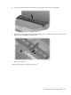
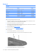
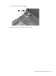
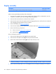
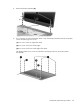
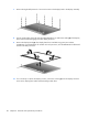
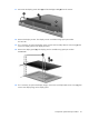
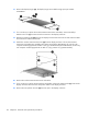
Table Of Contents
- Product description
- External component identification
- Illustrated parts catalog
- Removal and replacement procedures
- Setup Utility
- Specifications
- Computer specifications
- 15.4-inch, WXGA, BrightView display specifications
- Hard drive specifications
- DVD±RW and CD-RW SuperMulti Double-Layer Combo Drive specifications
- HD DVD-ROM Drive with SuperMulti DVD±R/RW Double Layer support specifications
- Blu-ray Disc ROM Drive with SuperMulti DVD±R/RW Double-Layer (DL) support specifications
- System DMA specifications, Intel
- System DMA specifications, AMD
- System interrupt specifications, Intel
- System interrupt specifications, AMD
- System I/O address specifications, Intel
- System I/O address specifications, AMD
- System memory map specifications, Intel
- System memory map specifications, AMD
- Screw listing
- Phillips PM2.0×5.0 captive screw
- Phillips PM3.0×3.0 screw
- Phillips PM2.0×3.0 screw
- Phillips PM2.5×7.0 screw
- Phillips PM2.5×10.0 screw
- Phillips PM2.5×4.0 screw
- Phillips PM2.5×3.0 screw
- Hex HM5.0×9.0 standoff
- Phillips PM2.0×2.0 screw
- Phillips PM2.0×7.0 screw
- Phillips PM2.5×5.0 captive screw
- Phillips 2.5×4.0 captive screw
- Backup and recovery
- Connector pin assignments
- Power cord set requirements
- Recycling
- Index
Keyboard
Description
For use in: Spare part
number
For use in: Spare part
number
Finland, Norway, and Sweden 441428-DH1 Saudi Arabia 441428-171
France 441428-051 Spain 441428-071
French Canada 441428-121 Taiwan 441428-AB1
International 441428-B31 Thailand 441428-281
Italy 441428-061 Turkey 441428-141
South Korea 441428-AD1 The United Kingdom 441428-031
Latin America 441428-161 The United States 441428-001
Before removing the keyboard, follow these steps:
1.
Shut down the computer. If you are unsure whether the computer is off or in Hibernation, turn the
computer on, and then shut it down through the operating system.
2.
Disconnect all external devices connected to the computer.
3.
Disconnect the power from the computer by first unplugging the power cord from the AC outlet and
then unplugging the AC adapter from the computer.
4.
Remove the battery (see
Battery on page 41).
5.
Remove the switch cover (see
Switch cover on page 52).
Remove the keyboard:
1.
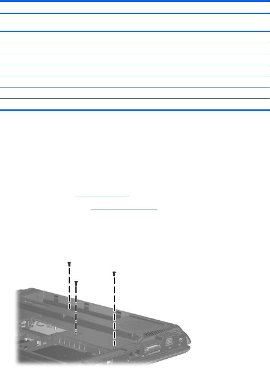
Turn the computer upside down, with the front toward you.
2.
Remove the three Phillips PM2.5×7.0 screws that secure the keyboard to the computer.
3.
Turn the computer display-side up, with the front toward you.
54 Chapter 4 Removal and replacement procedures