
Operation Manual
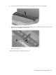
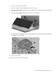
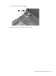
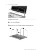
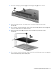
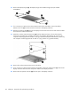
Table Of Contents
- Product description
- External component identification
- Illustrated parts catalog
- Removal and replacement procedures
- Setup Utility
- Specifications
- Computer specifications
- 15.4-inch, WXGA, BrightView display specifications
- Hard drive specifications
- DVD±RW and CD-RW SuperMulti Double-Layer Combo Drive specifications
- HD DVD-ROM Drive with SuperMulti DVD±R/RW Double Layer support specifications
- Blu-ray Disc ROM Drive with SuperMulti DVD±R/RW Double-Layer (DL) support specifications
- System DMA specifications, Intel
- System DMA specifications, AMD
- System interrupt specifications, Intel
- System interrupt specifications, AMD
- System I/O address specifications, Intel
- System I/O address specifications, AMD
- System memory map specifications, Intel
- System memory map specifications, AMD
- Screw listing
- Phillips PM2.0×5.0 captive screw
- Phillips PM3.0×3.0 screw
- Phillips PM2.0×3.0 screw
- Phillips PM2.5×7.0 screw
- Phillips PM2.5×10.0 screw
- Phillips PM2.5×4.0 screw
- Phillips PM2.5×3.0 screw
- Hex HM5.0×9.0 standoff
- Phillips PM2.0×2.0 screw
- Phillips PM2.0×7.0 screw
- Phillips PM2.5×5.0 captive screw
- Phillips 2.5×4.0 captive screw
- Backup and recovery
- Connector pin assignments
- Power cord set requirements
- Recycling
- Index

7.
Remove the eight Phillips PM2.5×7.0 screws that secure the display bezel to the display assembly.
8. Flex the inside edges of the left and right sides (1) and the top and bottom sides (2) of the display
bezel until the bezel disengages from the display enclosure.
9. Remove the display bezel (3). The display bezels are available using spare part numbers
433283-001 and 453328-001 for models with Intel processors, and 433284-002 for full-featured
models with AMD processors.
10. If it is necessary to replace the display inverter, remove the inverter (1) from the display enclosure
as far as the display panel cable and the backlight cable allow.
60 Chapter 4 Removal and replacement procedures