
Operation Manual
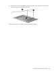

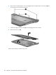

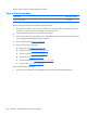
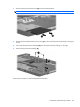


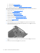
Table Of Contents
- Product description
- External component identification
- Illustrated parts catalog
- Removal and replacement procedures
- Setup Utility
- Specifications
- Computer specifications
- 15.4-inch, WXGA, BrightView display specifications
- Hard drive specifications
- DVD±RW and CD-RW SuperMulti Double-Layer Combo Drive specifications
- HD DVD-ROM Drive with SuperMulti DVD±R/RW Double Layer support specifications
- Blu-ray Disc ROM Drive with SuperMulti DVD±R/RW Double-Layer (DL) support specifications
- System DMA specifications, Intel
- System DMA specifications, AMD
- System interrupt specifications, Intel
- System interrupt specifications, AMD
- System I/O address specifications, Intel
- System I/O address specifications, AMD
- System memory map specifications, Intel
- System memory map specifications, AMD
- Screw listing
- Phillips PM2.0×5.0 captive screw
- Phillips PM3.0×3.0 screw
- Phillips PM2.0×3.0 screw
- Phillips PM2.5×7.0 screw
- Phillips PM2.5×10.0 screw
- Phillips PM2.5×4.0 screw
- Phillips PM2.5×3.0 screw
- Hex HM5.0×9.0 standoff
- Phillips PM2.0×2.0 screw
- Phillips PM2.0×7.0 screw
- Phillips PM2.5×5.0 captive screw
- Phillips 2.5×4.0 captive screw
- Backup and recovery
- Connector pin assignments
- Power cord set requirements
- Recycling
- Index

2. Remove the ExpressCard slot bezel (2) from the ExpressCard slot.
NOTE: The ExpressCard slot bezel is included in the Plastics Kit, spare part number 438669-001.
3. Remove the three Phillips PM2.5×4.0 screws (1) that secure the ExpressCard assembly to the system
board.
4. Disconnect the ExpressCard assembly (2) from the system board by sliding it to the right.
5. Remove the ExpressCard assembly (3).
Reverse this procedure to install the ExpressCard assembly.
Component replacement procedures 69