RAID Array 3000 Controller Shelf Hardware User’s Guide EK–SMCPQ–UG.
While Compaq Computer Corporation believes the information included in this manual is correct as of the date of publication, it is subject to change without notice. Compaq makes no representations that the interconnection of its products in the manner described in this document will not infringe existing or future patent rights, nor do the descriptions contained in this document imply the granting of licenses to make, use, or sell equipment or software in accordance with the description.
Warning! This is a Class A product. In a domestic environment this product may cause radio interference in which case the user may be required to take adequate measures. Achtung! Dieses ist ein Gerät der Funkstörgrenzwertklasse A. In Wohnbereichen können bei Betrieb dieses Gerätes Rundfunkstörungen auftreten, in welchen Fällen der Benutzer für entsprechende Gegenmaßnahmen verantwortlich ist. Attention! Ceci est un produit de Classe A.
Contents Revision Record ............................................................................................................................ vii About This Guide ..........................................................................................................................ix 1 Product Overview 1.1 Product Description ...........................................................................................................1–1 1.2 Shelf Features ......................................
RAID Array 3000 Controller Shelf 2 RAID Array Controller (continued) 2.6.3 2.6.4 2.6.5 2.6.6 2.7 RAID 0+1...................................................................................................................2–11 RAID 4 .......................................................................................................................2–13 RAID 5 .......................................................................................................................2–14 JBOD .................
Contents Figures 1–1 RAID Array 3000 Controller Shelf ..................................................................................1–2 1–2 RAID Array 3000 6-Slot Device Expansion Shelf..........................................................1–3 1–3 Controller Shelf Major Components ................................................................................1–6 1–4 RAID Array Controller......................................................................................................
RAID Array 3000 Controller Shelf Figures (continued) 3–15 Controller Shelf Field Replaceable Units......................................................................3–29 3–16 Replacing the Host I/O SBB ...........................................................................................3–30 3–17 Removing the Controller from the Shelf .......................................................................3–32 3–18 Replacing a Blower Assembly..........................................................
Revision Record This Revision Record provides a concise publication history of this guide. It lists the revision levels, release dates, and reasons for the revisions. The following revision history lists all revisions of this publication and their effective dates. The publication part number is included in the Revision Level column, with the last entry denoting the latest revision. This publication supports the StorageWorks RAID Array 3000 Controller Shelf.
About This Guide This section identifies the audience of this guide and describes the contents (chapter-bychapter) and structure. In addition, this section includes a list of associated documents and the conventions used in this guide. Intended Audience This guide is intended for installers and operators of the RAID Array 3000 Controller Shelf. Installing the shelf requires a general understanding of basic SCSI terminology and product installation procedures.
RAID Array 3000 Controller Shelf Chapter 4: Second Controller Option Second Controller Option describes how to install a second (redundant) RAID controller in the shelf for redundancy. It also contains a dual controller installation procedure for a single serial port.
About This Guide Conventions This guide uses the following documentation conventions: Table 2 Style Conventions Style Meaning plain monospace type Text boldface type For the first instance of terms being defined in text, or both. italic type For emphasis, manual titles, chapter summaries, keyboard key names.
RAID Array 3000 Controller Shelf Support and Services Who to contact in the Americas Information and Product Questions: Installation Support: Local Sales Office / StorageWorks Hotline 1-800-786-7967 Contact the COMPAQ Distributor where the Storage Solution was Purchased / Local Compaq Sales Office. Multivendor Customer Service (MCS): Installation Contact the Compaq Customer Support Center (CSC).
1 Product Overview This chapter provides an overall description of the RAID Array 3000 Controller Shelf and its components. A series of cabling diagrams showing how to connect the Controller Shelf to a host system and a list of technical and environmental specifications is also included at the end of the chapter. NOTE This guide is the Hardware User’s Guide.
RAID Array 3000 Controller Shelf NOTE The Device Expansion Shelf (DS-SWXRA-GN) must have a revision level of B01 (or higher) to operate with the RAID Array 3000 Controller Shelf. Also, the Personality I/O module supplied with the shelf (part no. 70-33067-02) must have a minimum revision level of H01 or higher. The Controller Shelf and the accompanying Device Expansion Shelves are installed in a standard RETMA or metric rackmount cabinet design.
Chapter 1. Product Overview Figure 1–2 RAID Array 3000 6-Slot Device Expansion Shelf (Optional) SHR-1091 A battery-backup subsystem is included with the Controller Shelf in the form of a rackmount UPS (Uninterruptable Power Supply). In case of a power failure, the UPS provides temporary power to the storage system while it flushes its cache contents to disks. The UPS is normally installed in the lowest available slot in the cabinet.
RAID Array 3000 Controller Shelf Table 1–1 Controller Shelf Part Numbers and Model Descriptions DIGITAL Part No.
Chapter 1. Product Overview 1.2 Shelf Features The RAID 3000 Controller Shelf is equipped with a dual-channel RAID controller that supports all of the UltraSCSI bus features.
RAID Array 3000 Controller Shelf Figure 1–3 shows the major components in the controller shelf. Its characteristics are outlined below. • An easily removable, two channel, resident RAID Array controller and an adjacent empty slot for a second (redundant) controller (optional) • There are two 68-pin VHDCI female SCSI connectors on the front panel of the device I/O assembly which interconnect the RAID controller to the SCSI buses in each storage shelf.
Chapter 1. Product Overview 1.4 Shelf Cabinet Installation The Controller Shelf can be mounted in a StorageWorks metric or RETMA style cabinet. You must install the appropriate shelf rail kit hardware to properly mount the shelf in the cabinet. The RETMA rail kit is supplied with the shelf and contains the installation guide which describes the installation procedure. The rail kit for a metric cabinet is optional.
RAID Array 3000 Controller Shelf The controller supports one (for a single controller) or two (for dual-controllers) standard 72-pin cache SIMMs of up to 64 MB. In a dual-controller setup, both controllers must have identical cache configurations and the total usable cache (per controller) will be half the amount installed due to mirroring. Thus, in a single controller setup the maximum usable cache is 128 MB while a redundant setup has a maximum usable cache of 64 MB (per controller).
Chapter 1. Product Overview • Two-speed blower operation • SBB shelf blower control to include error detection, reporting, and automatic corrective action Figure 1–5 Device I/O Module Upper Mounting Tab Device Port 0 Connector Device Port 1 Connector Lower Mounting Tab SHR-1045 The dual-channel device I/O module has two 68-pin VHDCI female connectors mounted on the front panel (see Figure 1–5). The upper connector is the “device port 0” connector.
RAID Array 3000 Controller Shelf Figure 1–6 Device I/O Module Blower Status LEDs Left Blower LED SCSI Bus Address Switch S3 (Not Used) Right Blower LED SCSI Bus Termination Switch S4 SHR-1046 NOTE The SCSI bus address switch on the Controller Shelf device I/O module does not control the target addresses of the SBB slots in the Device Expansion Shelves. This switch has been electrically disabled by design.
Chapter 1. Product Overview Figure 1–7 Host I/O Module Host Out Host In CTR UPS SHR-1036 The front panel of the host I/O module contains two 68-pin VHDCI SCSI connectors and two 9-pin D connectors. The SCSI connectors provide the SCSI bus connections between the adapter in the host system and the controller(s) in the Shelf. One of the 9-pin D connectors interfaces the UPS status signals to the controller.
RAID Array 3000 Controller Shelf 1.5.4 Shelf Cooling The device I/O module ensures that the SBBs and Controller Shelf are at the proper operating temperature by monitoring the operational status of the blowers and sensing the ambient air temperature. The two dual-speed blowers cool all the shelf components by drawing ambient air in through the front of the SBBs and exhausting it out the rear of the Controller Shelf. The blowers normally operate at low speed.
Chapter 1. Product Overview Figure 1–8 Power Supply SHR-1034 1.5.6 Uninterruptable Power Supply (UPS) The primary function of the UPS is to keep the entire storage system powered-up to enable the controller(s) to flush cache to disks. The UPS also protects the storage system from problems associated with poor quality AC power or a complete loss of AC power. The UPS is normally mounted in a lower shelf slot in the cabinet using a custom set of mounting brackets.
RAID Array 3000 Controller Shelf 1.6 6-Slot Device Expansion Shelf (Optional) NOTE The Device Expansion Shelf (DS-SWXRA-GN) must have a revision level of B01 (or higher) to operate with the RAID Array 3000 Controller Shelf. Also, the Personality I/O module supplied with the shelf (part no. 70-33067-02) must have a minimum revision level of H01 or higher. The RAID Array 3000 Controller Shelf is designed to operate with the StorageWorks BA356-S Series Device Expansion Shelf (shown in Figure 1–2.
Chapter 1.
RAID Array 3000 Controller Shelf Figure 1–10 Single Host, Single Adapter, with Two Active Controllers 2 Host System Host Adapter SHR-1317 1 BA356 Device Expansion Shelves 2 Host In Connector on H0 I/O Module 3 RAID Array 3000 Controller Shelf 4 SCSI Cable BN37A-05 (host adapter connection made using Technology Adapter cable BN38E-OB, not shown) 5 SCSI Cable BN37A-OE combining Host Modules H0 and H1 6 Host In Connector on H0 I/O Module 7 Host In Connector on H1 I/O Module 8 H1 Host I/O M
Chapter 1.
RAID Array 3000 Controller Shelf Figure 1–12 Dual Host, Single Adapter, with One Active Controller per Host Host System Host Adapter Host System Host Adapter SHR-1319 1–18 1 BA356 Device Expansion Shelves 2 RAID Array 3000 Controller Shelf 3 SCSI Cable BN37A-05 (host adapter connection made using Technology Adapter cable BN38E-OB, not shown) 4 SCSI Cable BN37A-05 (host adapter connection made using Technology Adapter cable BN38E-OB, not shown) 5 Host In Connector on H0 I/O Module 6 Host In
Chapter 1. Product Overview 7 SCSI Cables BN37A-OE (2) for Device I/O Module 0 8 SCSI Cables BN37A-OE (2) for Device I/O Module 1 1.
RAID Array 3000 Controller Shelf Table 1–2 Shelf Technical Specifications (continued) Feature Maximum I/O per second Sustained Raid 5 I/O rate -- 2 KB block transfers RAID levels supported Description 4,400 I/O per second Non-RAID disk support (JBOD) Reconstruct time Yes Configurable with SWCC Stripe size / chunk size Variable Maximum Logical Drives (LUNs) Up to 30 RAID sets Up to 16 redundancy groups (LUNs) per RAID set Maximum disk/ RAID sets Boot from RAID set Two, 32 blocks. Theoretical 2.
Chapter 1. Product Overview Table 1–2 Shelf Technical Specifications (continued) Feature Description Regulatory approvals EMI/R I -- FCC Class A, CSA 108.8 Class A, VCCI level 1, BICQ Class A, CISPR-22 Class A, C-Tick Class A rd Safety -- UL 1950 3 edition, AS/NZ 3260, IEC 950 CSA 22.
2 RAID Array Controller This chapter describes the major features and characteristics of the RAID array controller in the controller shelf. 2.1 Controller Overview The RAID Array controller provides high performance, high-availability access to SCSI disk array subsystems along a wide UltraSCSI bus. With a modular hardware design and an intuitive configuration utility, the controller is designed to meet a wide range of storage needs.
RAID Array 3000 Controller Shelf Figure 2–1 RAID Array 3000 Single Controller Block Diagram Ultra SCSI Differential, Wide Interface Host System 0 RAID Array 3000 Controller Shelf Host System 1 H0 H1 Host I/O Assy RAID Controller UPS Control Interface Cache Interface Write-Back Cache Module Controller / Bus Modules To UPS CTR Serial Interface 2 Device Ports Maintenance PC Ultra SCSI Wide Single-Ended Interface Device I/O Assy Port 0 Port 1 Device Storage Shelves 2–2 SHR-1050 EK–SMCPQ–UG.
Chapter 2. RAID Array Controller There are two configurations for redundant pairs of controllers: Active/Active Failover mode and Active/Passive Failover mode. In Active/Active Failover, each controller in the redundant pair has one active SCSI host port and one passive SCSI host port. Redundancy Groups (Virtual LUNS) can be mapped only to one active host port and are not accessible from the passive port or the other controller (i.e. partitioned model).
RAID Array 3000 Controller Shelf From the storage shelf’s perspective, the controller receives the I/O requests from the host and directs them to the devices. Since the controller processes all the I/O requests, it eliminates the host-based processing that is typically associated with reading and writing data to multiple storage devices.
Chapter 2. RAID Array Controller 2.
RAID Array 3000 Controller Shelf Figure 2–4 Controller Front Panel Reset H0 H1 D0 D1 F ault Reset H0 H1 D0 D1 Fault SHR-1049 2.4 Flexible RAID Set Configuration In addition to its flexible hardware design, the controller’s firmware offers the user the flexibility to configure RAID sets in several different ways: 2–6 • RAID sets can comprise drives from any drive channel and SCSI ID.
Chapter 2. RAID Array Controller 2.5 Performance Enhancements The controller employs a number of techniques to achieve as much performance as possible from its design. 2.5.1 Custom Components To increase performance and reliability, the controller’s core functions have been encapsulated in four custom ASIC (Application Specific Integrated Circuits) components as follows: XOR ASIC: Used in the Exclusive -Or parity calculations employed by RAID levels 4 and 5.
RAID Array 3000 Controller Shelf 2.5.2.1 Write-Back Caching When the host sends data to be written to a redundancy group the controller stores the data in its cache and immediately reports to the host it has completed the write. The controller eventually writes the data to the disk drives when the write can be done most efficiently, or when the controller must flush the cache to make room for other data or to prepare for a shutdown.
Chapter 2. RAID Array Controller There are some restrictions you must adhere to when creating a RAID set using the RAID 3000 shelf. The minimum and maximum number of drives required to support each RAID level is listed in Table 2–3. Table 2–3 Shelf RAID Set Restrictions * RAID Level Min. No. of Drives Max. No. of Drives JBOD 1 1 0 2 24 1 2 24 0+1* 4 16 4 3 24 5 3 24 Must be even number. 2.6.
RAID Array 3000 Controller Shelf Figure 2–5 RAID 0 Write Host Data 1011 0110 1010 0101 0000 0001 1100 1111 0111 1010 Controller divides the data into chunksized units 1011 0110 1010 0101 0000 Striped data written to the array There is still data left so the Controller repeats the process 0001 1100 1111 0111 1010 Striped data written to the array SHR-1054 2–10 EK–SMCPQ–UG.
Chapter 2. RAID Array Controller 2.6.2 RAID 1 RAID 1 (also known as mirroring or shadowing) takes data sent by the host and duplicates it on all the drives in an array. The result is a high degree of data availability, since you can lose all but one drive in the array and still have full access to your data. This comes at a price: a RAID 1 array requires multiple drives to achieve the storage capacity of a single drive. Figure 2–6 illustrates a RAID 1 write.
RAID Array 3000 Controller Shelf Figure 2–7 Diagram of RAID 0+1 Write Host Data 1110 1101 1011 Controller divides the data into chunksized units 1110 1101 1011 Striped data written to half the drives Striped data mirrored to the remaining drives SHR-1056 In the event of a drive failure, a RAID 0+1 array will enter degraded mode and continue to operate by substituting the failed drive with its mirror. When the controller creates a RAID 0+1 set, it first sorts the drives by channel number and SCSI ID.
Chapter 2. RAID Array Controller 2.6.4 RAID 4 RAID 4 (Figure 2–8) breaks up host data into chunks, calculates parity by performing an exclusive-or on the chunks, and then writes the chunks to all but one drive in the array and the parity data to the last drive. When the host requests data from the disk drives, the controller retrieves the chunks containing the addressed data, reconstitutes the data from the chunks, and passes the data to the host.
RAID Array 3000 Controller Shelf In the event of a single drive failure, a RAID 4 array will continue to operate in degraded mode. If the failed drive is a data drive, writes will continue as normal, except no data will be written to the failed drive. Reads will reconstruct the data on the failed drive by performing an exclusive-or operation on the remaining data in the stripe and the parity for that stripe.
Chapter 2.
RAID Array 3000 Controller Shelf While RAID 5 is ideally suited for applications with many, small I/O operations, there is no reason why it cannot function equally well for applications with large, sequential I/O operations. This makes RAID 5 an excellent all-purpose RAID level. CAUTION RAID 5 can withstand a single failure and handle I/O activity without interruption in degraded mode until the failed drive is rebuilt.
Chapter 2. RAID Array Controller When one controller fails, the survivor will process all I/O requests until the failed controller is repaired and powered on. The subsystem will then return to its previous state (i.e., ACTIVE / ACTIVE or ACTIVE / PASSIVE). 2.8.1 Initialization During initialization, the firmware in the RAID 3000 verifies that both controllers have consistent configurations including identical memory cache and system parameters.
RAID Array 3000 Controller Shelf 2.9 Environmental The controller incorporates a set of on board sensors to detect abnormal operating conditions that may affect data safety. 2.9.1 Backup Power Management The controller must be connected to the Uninterruptable power supply (UPS) to prevent the subsystem cache from being corrupted during unexpected losses of power.
3 Installation and Maintenance This chapter describes how to install the Controller Shelf in a RETMA or metric-style storage cabinet and then make the cable connections to the UPS, Device Expansion Shelves and host system. The maintenance section describes how to interpret the status of the LEDs on the front panel of the Controller Shelf. The chapter also describes how to replace a Field Replaceable Unit (FRU). 3.
RAID Array 3000 Controller Shelf 3.2 • Install the UPS below the shelves and as low as possible in the cabinet. • Ensure there is a approximate two-inch gap between the bottom of the controller shelf and the UPS to allow cable routing between the front panel connectors and connectors at the back of the units.
Chapter 3. Installation and Maintenance Figure 3–1 Recommended Single Expansion Shelf Installation P / S P / S P / S P / S 5 4 3 2 1 Device Expansion Shelf 0 Controller Shelf UPS SHR-1096 EK–SMCPQ–UG.
RAID Array 3000 Controller Shelf Figure 3–2 Recommended Controller Shelf Installation (Two Expansion Shelves) P / S P / S P / S P / S P / S P / S 5 4 3 2 1 0 5 4 3 2 1 0 SHR-1097 3–4 EK–SMCPQ–UG.
Chapter 3. Installation and Maintenance Figure 3–3 Recommended Controller Shelf Installation (Three Expansion Shelves) P / S P / S P / S 13 12 11 10 9 8 P / S 5 4 3 2 1 0 P / S P / S 5 4 3 2 1 0 P / S P / S SHR-1098 EK–SMCPQ–UG.
RAID Array 3000 Controller Shelf Figure 3–4 Recommended Installation (Four Expansion Shelves) P / S P / S 13 12 11 10 9 8 P / S P / S 13 12 11 10 9 8 P / S P / S 5 4 3 2 1 0 P / S P / S 5 4 3 2 1 0 P / S P / S SHR-1099 3–6 EK–SMCPQ–UG.
Chapter 3. Installation and Maintenance 3.2.1 Installing Shelf Supports After you determine the desired shelf slot locations in your cabinet, install the shelf support mounting kits supplied with the shelves. Shelf support mounting kits for the RETMA and metric style cabinets are included with each shelf assembly. The UPS is rack mounted using custom adjustable rail brackets.
RAID Array 3000 Controller Shelf 2. Determine the mounting location in your cabinet. 3. Install the left shelf support by aligning the bracket and cabinet rail holes and then securing the support to the cabinet using two screws (item 7, Figure 3–5). Do not tighten screws. 4. Install the nut plate (item 5, Figure 3–5) behind the left rail and secure with three screws. Tighten all five screws. 5. Repeat steps 2, 3, and 4 to install the right shelf support in the cabinet. 6.
Chapter 3. Installation and Maintenance 8. Repeat step 7 to secure a shelf retainer bracket to the right shelf support. 9. Place the Controller Shelf on the cabinet shelf supports and slide the shelf completely to the rear of the cabinet. 10. Install two shelf retainer brackets (item 1, Figure 3–5) to the left and right rails of the cabinet and secure with two screws. The Controller Shelf is now safely mounted in the cabinet. Figure 3–5 RETMA Cabinet Shelf Supports 3.2.
RAID Array 3000 Controller Shelf Table 3–3 UPS Rack-mount Bracket Mounting Hardware List Cabinet Style Hardware Item Part Number RETMA (round hole) Screw 90-00063-39 U-Nut 90-07786-00 Screw 90-40331-01 Cage Nut 90-11476-01 Washer 90-0664-00 RETMA (square hole) Figure 3–6 shows the left and right-hand UPS bracket assemblies. Figures 3–7 and 3–8 illustrate the front and rear bracket mounting holes for both cabinet designs. Refer to these figures throughout the bracket installation procedure.
Chapter 3. Installation and Maintenance Figure 3–6 UPS Rack-mount Bracket Assemblies Figure 3–7 UPS Bracket RETMA and Metric Hole Locations (Front) EK–SMCPQ–UG.
RAID Array 3000 Controller Shelf 4. Pull and extend the rear bracket assembly until it reaches the hole mounting channel at the rear of the cabinet and install cage nuts (or U-nuts) at the rear of the rail into the corresponding holes in the cabinet (see Figure 3–7). Extend the bracket beyond rail and tighten the hardware to secure the bracket to the cabinet. 5. Install the UPS right-hand bracket on the right side of the cabinet using the same hole patterns and hardware used in steps 2 and 3. 6.
Chapter 3. Installation and Maintenance 3.3 Power and SCSI Cable Connection Procedures This section contains the power and SCSI cabling procedures for a single or multiple Device Expansion Shelf subsystem installation. Each procedure describes how to connect the Controller Shelf to the Device Expansion Shelve(s), the host system, the UPS, and the maintenance PC.
RAID Array 3000 Controller Shelf 3.3.1 SCSI Bus Target Addresses and Termination NOTE The SCSI bus address switch on the Controller Shelf device I/O module has been disabled. It does affect or control the SCSI bus addresses of the devices in the Device Expansion Shelves. The target addresses of the disk drives are set by address switch S3 on the personality module in each Device Expansion Shelf.
Chapter 3. Installation and Maintenance 3.3.2 Cabling a Single Device Expansion Shelf Subsystem (See Figures 3–9 and 3–10) 1. Ensure the physical installation phase of installing and securing shelf brackets and shelves (including the UPS) has been accomplished and that the shelves are secured within the shelf bracket the shelf lock provided. 2. Remove the device I/O module from the Controller Shelf and ensure the switch positions of SCSI bus termination switch S4 are set as shown in Figure 3–9.
RAID Array 3000 Controller Shelf 12. After the UPS has been set to the correct input voltage level, set the UPS low-battery warning option to five minutes (refer to UPS manual for instructions). 13. This completes the Controller and Device Expansion Shelf cabling procedure. Dress and ty-wrap related cable groups, and then refer to the RAID Array 3000 Getting Started and Command Console Installation and User Guides for information describing how to setup and configure your subsystem.
Chapter 3. Installation and Maintenance Figure 3–10 AC Power Wiring Diagram To Device Expansion Shelves 2, 3, and 4 DEVICE EXPANSION SHELF #1 P/S A P/S B CONTROLLER SHELF P/S A Host 0 I/O Module P/S B UPS UPS Control (17-04729-01) Gray Power Cords AC Power Receptacles UPS Black Power Cords AC Power Source SHR-1116 EK–SMCPQ–UG.
RAID Array 3000 Controller Shelf 3.3.3 Cabling a Two Device Expansion Shelf Subsystem (See Figures 3–10 and 3–11) 1. Ensure the physical installation phase of installing and securing shelf brackets and shelves (including the UPS) has been accomplished and that the shelves are secured within the shelf bracket the shelf lock provided. 2. Remove the device I/O module from the Controller Shelf and ensure the switch positions of SCSI bus termination switch S4 are set as shown in Figure 3–9.
Chapter 3.
RAID Array 3000 Controller Shelf CAUTION To prevent possible damage to the equipment, the input voltage level of the UPS must be set to your specific line voltage before proceeding. Refer to the UPS manual and set the input level to your ac power source(s). 13. After the UPS has been set to the correct voltage level, set the UPS lowbattery warning option to five minutes (refer to UPS manual for instructions). 14. This completes the Controller and Device Expansion Shelf cabling procedure.
Chapter 3. Installation and Maintenance 3.3.4 Cabling a Three Device Expansion Shelf Subsystem (See Figures 3–10 and 3–12) 1. Ensure the physical installation phase of installing and securing shelf brackets and shelves (including the UPS) has been accomplished and that the shelves are secured within the shelf bracket the shelf lock provided. 2. Remove the device I/O module from the Controller Shelf and ensure the switch positions of SCSI bus termination switch S4 are set as shown in Figure 3–9.
RAID Array 3000 Controller Shelf Figure 3–12 Controller/ Three Device Expansion Shelf Cabling Diagram DEVICE EXPANSION SHELF # 3 P/S A 1 2 3 4 5 6 7 SCSI Bus Address Switch (S3) Personality I/O Module OFF ON 1 2 3 4 SCSI Bus Termination Switch (S4) ON OFF 1 2 3 4 5 6 7 SCSI Bus Address Switch (S3) P/S B DEVICE EXPANSION SHELF # 1 P/S A ON OFF P/S B DEVICE EXPANSION SHELF # 2 P/S A Personality I/O Module OFF ON 1 2 3 4 SCSI Bus Termination Switch (S4) Personality I/O Module P/S B OFF ON 1
Chapter 3. Installation and Maintenance 13. Connect the UPS serial control cable (17-04729-01) from the UPS connector Controller Shelf host 0 I/O module to the like connector on the UPS. 14. Install jumper connector 12-49700-01 to the Controller Shelf UPS connector on the host 1 I/O module. CAUTION To prevent possible damage to the equipment, the input voltage level of the UPS must be set to your specific line voltage before proceeding.
RAID Array 3000 Controller Shelf 3.3.5 Cabling a Four Device Expansion Shelf Subsystem (See Figures 3–10 and 3–13) 1. Ensure the physical installation phase of installing and securing shelf brackets and shelves (including the UPS) has been accomplished and that the shelves are secured within the shelf bracket the shelf lock provided. 2. Remove the device I/O module from the Controller Shelf and ensure the switch positions of SCSI bus termination switch S4 are set as shown in Figure 3–9.
Chapter 3.
RAID Array 3000 Controller Shelf 13. Connect a 5-meter SCSI cable (BN37A-05) between the host-in connector on the Controller Shelf host 0 I/O module (bottom connector) and the corresponding connector on the host system. 14. Connect the maintenance serial control cable (17-04730-01) from the CTR 0 connector on the Controller Shelf host 0 I/O module to the corresponding connector on the maintenance PC. 15.
Chapter 3. Installation and Maintenance 3.4 Controller Shelf Status LEDs The Controller Shelf is equipped with two front-panel LEDs (see Figure 3–14) that monitor the following error conditions: • A shelf blower that is not operating • An over-temperature condition • A dc power problem • External fault conditions • Controller faults When the shelf is operating properly, the green power LED is on and the amber shelf fault LED is off.
RAID Array 3000 Controller Shelf 3.5 Controller LEDs The LEDs on the front panel of the controller monitor host and disk channel activity and a controller fault condition. The reset button/LED flashes green approximately once every second (heartbeat) to indicate that the controller is operating normally. Figure 2–3, Chapter 2, identifies the LEDs. Table 2–1 describes their functions. 3.6 Replacing Components (FRU’s) This section describes how to replace an FRU in the RAID Array 3000 controller shelf.
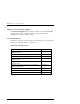
Chapter 3. Installation and Maintenance Figure 3–15 Controller Shelf Field Replaceable Units 5 1 2 3 4 SHR-1052 Table 3–4 Controller Shelf Field Replaceable Units Item Qty. Part Number Description 1 2 30-48191-04 Power Supply, 180 W, 50/60 Hz, +5 V, +12V, 2 1* 70-33523-01 RAID Controller 3 2 70-33525--01 Host I/O Module 4 1 70-33067-05 Device I/O Module 5 2 70-29761-07 Blower Assembly * Second (redundant) controller is optional EK–SMCPQ–UG.
RAID Array 3000 Controller Shelf 3.6.1 Replacing a Host or Device I/O SBB CAUTION When you remove an SBB, the airflow through the shelf is reduced. Always install the replacement unit immediately to prevent overheating. 1. Ensure the SCSI bus connected to the SBB is quiescent (no I/O activity). 2. Disconnect the cables (or jumper) from the front panel of the SBB. 3.
Chapter 3. Installation and Maintenance 3.6.2 Replacing a Power Supply SBB CAUTION When you remove a power supply, the airflow through the shelf is reduced. Always install the replacement unit immediately to prevent overheating. You can replace a dc power supply without affecting shelf operation using the following procedure: 1. Remove the ac input power cable from the shelf power supply. 2. Squeeze the mounting tabs to release the unit and pull it out of the shelf. 3.
RAID Array 3000 Controller Shelf 3.6.3 Replacing the RAID Controller CAUTION When you remove the controller, the airflow through the shelf is reduced. Always install the replacement unit immediately to prevent overheating. 1. Ensure the SCSI bus connected to the SBB is quiescent (no I/O activity). 2. Grip the two locking latches on the front panel of the controller and pull them forward until the controller disengages from its mounting slot (Figure 3–17). 3.
Chapter 3. Installation and Maintenance 3.6.4 Replacing the UPS Proceed as follows to replace the UPS: 1. Ensure the UPS power switch is set to off. 2. Disconnect the shelf power cords from the rear receptacles on the UPS. 3. Disconnect the UPS power cord from the wall outlet. 4. Disconnect the serial control cable from the controller shelf. 5. Remove the screws that secure the front panel of the UPS to the cabinet. 6.
RAID Array 3000 Controller Shelf If you can access the blowers from the rear of the cabinet, proceed as follows: 1. Use a Phillips-head screwdriver to remove the safety screw in the upper right corner or lower left corner of the blower (see Figure 3–18). 2. Press the upper and lower blower mounting tabs together to release the blower. Pull the blower straight out to disconnect it from the shelf power connector. 3. 4.
Chapter 3. Installation and Maintenance If you cannot access the blowers from the rear of the cabinet, proceed as follows: 1. Disconnect the cables from the front of the controller shelf and remove the shelf from the cabinet. 2. Use a Phillips-head screwdriver to remove the safety screw in the upper right corner or lower left corner of the blower. 3. Press the upper and lower blower mounting tabs together to release the blower. 4.
RAID Array 3000 Controller Shelf 1. Power down the controller shelf first (via SWCC) and then the UPS. 2. Grasp the latches on the front of the controller and pull them forward until the controller disengages from the shelf (see Figure 3–17). 3. Remove the controller from the shelf and place on a flat working surface. 4.
Chapter 3. Installation and Maintenance Figure 3–21 Remove Installed SIMM Modules CAUTION Ensure the “side 1” side of the two replacement SIMMs is facing toward you when installing the modules in the following step. 5. Installed the two replacement memory modules by aligning the module and connector pins (check alignment guide in center of module) and gently pivot the module the main controller board until it snaps into place (see Figures 3–18 and 3–19). 6. Replace the controller into the shelf. 7.
RAID Array 3000 Controller Shelf Figure 3–22 Install Replacement Modules Figure 3–23 Pivot Module Down to Secure 3–38 EK–SMCPQ–UG.
4 Second Controller Option This chapter describes how to install a second RAID controller in the RAID Array 3000 Controller Shelf. The second controller option adds a fail/safe feature to your storage subsystem. The chapter also contains a procedure describing how to configure the subsystem for dualcontroller operation when only one serial port is available on the host. 4.
RAID Array 3000 Storage Subsystem 4.2 Installing the Upgrade CAUTION To prevent an electrical discharge from damaging the SIMMs, always wear an ESD wrist or foot strap connected to a suitable ground when handling the memory modules. NOTE You can upgrade your firmware using the SCSI or network connection methods. These methods provide the fastest way to upgrade your firmware. To update your controller’s firmware, proceed as follows. 4.2.
Chapter 4. Second Controller Option Figure 4-1. Saving the Existing Configuration A saved configuration screen with a “Save to File” field appears as shown in Figure 4-2. The example in Figure 4-2 shows the file name as c:\config1. Enter your file name in the “Save to File” field and click on Save. EK–SMCPQ–UG.
RAID Array 3000 Storage Subsystem Figure 4-2. Saved Configuration . 4.2.2 Update Firmware CAUTION If the systems disk is on the RA3000, firmware cannot be upgraded with SWCC. Establish a temporary system disk on a disk drive outside the RA3000 and proceed with these instructions or follow the alternative shown in Section 4.2.2.2. 4.2.2.1 Update Firmware Using SWCC Start SWCC and choose SCSI or Network Connection.
Chapter 4. Second Controller Option A window will appear (see Figure 4-4) asking you to specify the firmware file that you want to load. This file resides on the CD supplied with the controller kit option. You can easily identify Firmware software by its .fdi extension. Enter the .fdi file name (for example, D:\firmware\xxx.fdi), then click Start Update. Upon completion of the Firmware update, the system will automatically reboot and update the controller’s firmware. Figure 4-4.
RAID Array 3000 Storage Subsystem 5. Reset the controller by power cycling the RA3000 subsystem. You should see a "Flash Boot Utility... " banner, followed by instructions to type CTRL/C to abort. Press CTRL/C to abort the load sequence. A "FLASH Boot Utility Options" menu should be displayed. 6. Choose menu item (2), Change serial baud rate. Select 38400.
Chapter 4. Second Controller Option 4.2.4 1. Install Two SIMMs into Second Controller Install two of the SIMM modules into the second controller (make sure all SIMM modules are of the same type) by aligning the connector pins and inserting the modules into the SIMM module connectors as shown in Figure 4-5. Figure 4-5. Insert Module into SIMM Connector 2. Ensure the module is firmly seated and then gently pivot it toward the controller board until it snaps into place as shown in Figure 4-6.
RAID Array 3000 Storage Subsystem 4.2.5 1. Replace Existing Controller Replace the existing controller (see Figure 4-7 to remove) with the new controller. Figure 4-7. Remove Controller from Top Slot SHR-1062 NOTE Ensure you install the new controller in the same slot as the existing controller removed in step 1 above. Do not leave the existing controller in the controller shelf while performing the following step. 2.
Chapter 4. Second Controller Option 4.2.6 Restore Configuration To restore your configuration to the new controller: 1. Restart SWCC in the “Serial Mode” (refer to your RA3000 Getting Started Guide for instructions). 2. Select the Storage pull-down menu from the Toolbar, then choose Controller. 3. From the Controller pull-down menu (Figure 4-8), select Configuration, and then Restore. Figure 4-8.
RAID Array 3000 Storage Subsystem Figure 4-9. Restored Configuration Example NOTE Restoring the configuration in the following step may take up to 5 minutes. Be patient. 4. Enter the file name that you saved in Section 4.2.1 and click on Restore. 4.2.7 1. After configuration has been restored, update firmware on the second controller. Repeat the procedure in Section 4.2.2.1 or 4.2.2.2. 2. After the configuration has been restored and firmware has been updated, power down the system. 4.2.
Chapter 4. Second Controller Option 4.3 Configuring a Dual Controller Installation for a Single Serial Port This section describes how to configure your RA3000 storage system for dual controller operation when only one serial port is available on the host. If required, refer to your Getting Started guide for SWCC installation instructions.
RAID Array 3000 Storage Subsystem 10. Restart the controllers by power cycling the RA3000 storage system. 11. Recheck the Rdnt Ctrlr Parameters. The controller Values should display Active/Passive. 12. Transfer the serial cable to the serial port on the top controller on the RA3000 and press Ctrl-Z. 13. Check the Rdnt Ctrlr Parameters. The controller Values should display Passive/Active. Your storage system is now properly configured for dual controller operation from a single serial host port.
Chapter 4. Second Controller Option 14. You have now created one Virtual Device (JBOD) on the top controller. Disconnect the serial cable from the top controller and reconnect the cable to serial port connector on the bottom (redundant) controller. 15. Close and reopen the StorageWorks window and repeat steps 4 through 13 above (Note: If the storage window connection is lost when the cable is moved, reopen the HSZ22 StorageWindow). 16.
RAID Array 3000 Storage Subsystem 4-14 1. Select the “Environment” tab from the Controller Properties window. 2. Ensure the cabinet and UPS settings are set to ‘normal’. 3. Select the Cache tab from the “Controller Properties” window. The SIMMs parameters must be identical between controllers. 4. Select OK. The system is now ready for dual-controller operation. Configuration of additional RAIDsets may now be performed as desired. EK–SMCPQ–UG.