ProLiant 3000 Servers For Use With Intel 350 MHz or Greater Processor-Based Servers Only Maintenance and Service Guide First Edition (February 1999) Part Number 113803-001 Spare Part Number 114651-001 Compaq Computer Corporation
Notice The information in this publication is subject to change without notice. COMPAQ COMPUTER CORPORATION SHALL NOT BE LIABLE FOR TECHNICAL OR EDITORIAL ERRORS OR OMISSIONS CONTAINED HEREIN, NOR FOR INCIDENTAL OR CONSEQUENTIAL DAMAGES RESULTING FROM THE FURNISHING, PERFORMANCE, OR USE OF THIS MATERIAL.
iii Contents About This Guide Symbols in Text.........................................................................................................................vii Compaq Technician Notes.........................................................................................................vii Where to Go for Additional Help .............................................................................................viii Integrated Management Display..................................................
iv Chapter 3 Diagnostic Tools Default Configuration...............................................................................................................3-2 Default Configuration Messages .......................................................................................3-2 Utilities Access.........................................................................................................................3-2 Running Compaq Utilities..........................................................
v Chapter 4 Connectors, Switches, Jumpers, and LEDs Connectors................................................................................................................................4-1 Rear Panel Connectors ......................................................................................................4-1 System I/O Board Connectors ...........................................................................................4-2 Switches..........................................................
vii About This Guide This Maintenance and Service Guide is a troubleshooting guide that can be used for reference when servicing Compaq ProLiant 3000 Servers. WARNING: To reduce the risk of personal injury from electrical shock and hazardous energy levels, only authorized service technicians should attempt to repair this equipment. Improper repairs could create conditions that are hazardous.
viii About This Guide WARNING: To reduce the risk of personal injury from electrical shock and hazardous energy levels, do not exceed the level of repair specified in these procedures. Because of the complexity of the individual boards and subassemblies, do not attempt to make repairs at the component level or to make modifications to any printed wiring board. Improper repairs could create conditions that are hazardous.
ix Telephone Numbers For the name of your nearest Compaq Authorized Reseller: In the United States, call 1-800-345-1518 In Canada, call 1-800-263-5868 For Compaq technical support: In the United States and Canada, call 1-800-386-2172 For Compaq technical support phone numbers outside the United States and Canada, visit the Compaq website at: http://www.compaq.com.
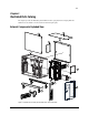
1-1 Chapter 1 Illustrated Parts Catalog This chapter provides the illustrated parts breakdown and a spare parts list for Compaq ProLiant 3000 Servers. See Table 1-1 for the names of referenced spare parts. External Components Exploded View 3b 2 3a 33a 1 33b 18b 47 18a 5 8 6 4 7 Figure 1-1.
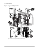
1-2 Illustrated Parts Catalog System Components Exploded View 12 23 13 35 1 26 10 17 16 20 21 40 22 9 15 44 14 43 19 Figure 1-2.
1-3 Spare Parts List Table 1-1 Spare Parts List - Compaq ProLiant 3000 Servers Ref Description Spare Part # 1 Chassis 306574-001 2 Side Access Panel 298364-001 3 Access Panel Kit a) U-Channel Access Panel b) Top Access Panel 327835-001 4 Front Bezel Door 298360-001 5 Fixed Front Bezel (Tower Model Only) 298361-001 6 Rack-Mount Bezel Plate 298363-001 7 Locking Casters 296227-001 8 Caster Mounting Support 330485-001 CHASSIS SYSTEM COMPONENTS 9 Front Fans (2) 306576-001 10 Rear
1-4 Illustrated Parts Catalog Spare Parts List Continued Ref Description Spare Part # MASS STORAGE DEVICES 22 32x IDE CD-ROM Drive with Tray 328707-001 23 1.
1-5 Spare Parts List Continued Ref Description Spare Part # 40 Smart Array 3200 Controller 340855-001 41 Processor, 450/100 MHz 179780-001 * 42 SCSI Duplex Hot-Plug Drive Cage 306572-001 * 43 Ultra2 Drive Cage 367087-001 44 9.1-GB Ultra2 Hard Drive with Tray 313715-001 45 18.2-GB Wide-Ultra Hard Drive with Tray 313764-001 * 46 9.1-GB Wide-Ultra Hard Drive with Tray 199888-001 * 47 4.3-GB Wide-Ultra Hard Drive with Tray (1-inch) 242622-001 48 2.
2-1 Chapter 2 Removal and Replacement Procedures This chapter provides subassembly/module-level removal and replacement procedures for ProLiant 3000 Servers. After completing all necessary removal and replacement procedures, run the Diagnostics program to verify that all components operate properly.
2-2 Removal and Replacement Procedures Symbols in Equipment WARNING: Any surface or area of the equipment marked with these symbols indicates the presence of a hot surface or hot component. If this surface is contacted, the potential for injury exists. To reduce risk of injury from a hot component, allow the surface to cool before touching. WARNING: Any surface or area of the equipment marked with these symbols indicates the presence of electrical shock hazards.
2-3 Rack Warnings WARNING: Always load the heaviest item first and load the rack from the bottom up. This makes the rack “bottom-heavy” and helps prevent the rack from becoming unstable. WARNING: To reduce the risk of personal injury, fire, or damage to the equipment, do not overload the AC supply branch circuit that provides power to the rack. WARNING: To reduce the risk of personal injury or damage to the equipment, the bottom stabilizers on the equipment must be fully extended.
2-4 Removal and Replacement Procedures Server Warnings and Precautions WARNING: To reduce the risk of personal injury or damage to the server, you must support the server when loading or unloading it from the rack. The server is not attached to the support rails of the rack and may fall if not supported when extended from the rack. WARNING: To reduce the risk of personal injury from hot surfaces, allow the internal system components to cool before touching.
2-5 Locking Casters To remove the locking casters: 1. Perform the preparation procedures. See “Preparation Procedures” earlier in this chapter. 2. Place the server on its side. 3. Remove the three T-25 screws securing each caster to the caster mounting support. 4. Pull the locking casters away from the server. Figure 2-1. Removing the locking casters Reverse steps 1 through 4 to replace the casters.
2-6 Removal and Replacement Procedures Caster Mounting Support To remove the caster mounting support: 1. Perform the preparation procedures. See “Preparation Procedures” earlier in this chapter. 2. Remove the casters. See “Locking Casters” earlier in this chapter. 3. Remove the four T-15 screws securing the caster mounting support to the server. 4. Pull the caster mounting support away from the server. Figure 2-2.
2-7 Front Bezel Door To remove the front bezel door (tower model only): 1. Swing the front bezel door open approximately 45 degrees. 2. Lift the front bezel door up, then pull it away from the chassis. COMPACT Figure 2-3. Removing the front bezel door NOTE: Drive cage may not be as illustrated. Reverse steps 1 and 2 to replace the front bezel door.
2-8 Removal and Replacement Procedures Front Fixed Bezel The front fixed bezel must be removed to replace the power switch. To remove the front fixed bezel (tower model only): 1. Perform the preparation procedures. See “Preparation Procedures” earlier in this chapter. 2. Open the front bezel door. 3. Remove the seven T-15 screws securing the front fixed bezel to the chassis. 4. Pull the front fixed bezel away from the chassis. COMPACT Figure 2-4.
2-9 Rack-Mount Bezel The rack-mount bezel (rack model only) must be removed to replace the power switch. To remove the rack-mount bezel: 1. Perform the preparation procedures. See “Preparation Procedures” earlier in this chapter. 2. Remove the seven T-15 screws securing the rack-mount bezel to the chassis. 3. Pull the rack-mount bezel away from the chassis. Figure 2-5. Removing the rack-mount bezel NOTE: Drive cage may not be as illustrated.
2-10 Removal and Replacement Procedures Top Access Panel WARNING: To reduce the risk of personal injury from hot surfaces, allow the internal system components to cool before touching them. To remove the top access panel (tower model only): 1. Perform the preparation procedures. See “Preparation Procedures” earlier in this chapter. 2. Open the front bezel door. 3. Remove the T-15 screw securing the top access panel to the front of the chassis. 4.
2-11 U-Channel Access Panel The U-channel access panel is removed for replacement only. To remove the U-channel access panel: 1. Perform the preparation procedures. See “Preparation Procedures” earlier in this chapter. 2. Pull the drive cage assembly forward until it clears the front edge of the U-channel access panel. See “Drive Cage Assembly” later in this chapter. 3. Remove the caster mounting support. See “Caster Mounting Support” earlier in this chapter. 4.
2-12 Removal and Replacement Procedures Side Access Panel WARNING: To reduce the risk of personal injury from hot surfaces, allow the internal system components to cool before touching them. To remove the side access panel: 1. Perform the preparation procedures. See “Preparation Procedures” earlier in this chapter. 2. Loosen the two screws at the front on the chassis with either a T-15 or Phillips screwdriver. 3. Slide the side access panel backward, then pull it away from the chassis.
2-13 Integrated Management Display (IMD) The IMD is removed for replacement only. NOTE: The IMD is shipped standard in the rack-mount model and as an option in the tower model. The tower model is shown. To remove the IMD: 1. Perform the preparation procedures. See “Preparation Procedures” earlier in this chapter. 2. Remove the front bezel door. See “Front Bezel Door” earlier in this chapter (tower model only). 3. Remove the front fixed bezel. See “Front Fixed Bezel” earlier in this chapter. 4.
2-14 Removal and Replacement Procedures 7. Press the four latches on the rear of the IMD 3. 8. Pull the IMD from the front of the server 4. 3 CT COMPA 3 3 4 3 Figure 2-10. Removing the Integrated Management Display NOTE: Drive cage may may not be as illustrated. Reverse steps 1 through 8 to replace the IMD. CAUTION: Make sure all power and signal cables to the drive cage assembly are reseated properly.
2-15 Fans Compaq ProLiant 3000 Servers ship standard with two 120-mm front fans (in positions 1 and 3) and one 92-mm rear fan (in position 5). The figure below shows the location of the front and rear fans in the ProLiant 3000 Server. You can add two fans for redundancy in the positions marked Fan 2 and Fan 4. IMPORTANT: Redundant fans must be added in pairs. Fan 1 (CPU) Fan 2 (CPU Redundant) Fan 5 (CPU Aux) Fan 3 (I/O) Fan 4 (I/O Redundant) Figure 2-11.
2-16 Removal and Replacement Procedures Front Fan(s) The front fans are removed for replacement or to replace the Integrated Management Display, the fan baffle, or the drive cage. To remove a front fan(s): 1. Perform the preparation procedures. See “Preparation Procedures” earlier in this chapter. 2. Remove the side access panel. See “Side Access Panel” earlier in this chapter. 3. Disconnect the fan cable from the system I/O board. 4. Push up on the latch on the side of the fan 1. 5.
2-17 Fan Baffle The fan baffle should only be removed if damaged. To remove the fan baffle: 1. Perform the preparation procedures. See “Preparation Procedures” earlier in this chapter. 2. Remove the side access panel. See “Side Access Panel” earlier in this chapter. 3. Remove fan 2. See “Front Fan(s)” earlier in this chapter. 4. Unsnap the two pins 1 on the fan baffle. 5. Pull the fan baffle back 2, then out and up from the side of the chassis. 1 2 Figure 2-13.
2-18 Removal and Replacement Procedures Rear Fan Remove the rear fan for replacement or for upgrading to another model fan. To remove the rear fan: 1. Perform the preparation procedures. See “Preparation Procedures” earlier in this chapter. 2. Remove the side access panel. See “Side Access Panel” earlier in this chapter. 3. Disconnect the rear fan cable from the system I/O board. 4. Loosen the thumbscrew securing the rear fan to the chassis. 5. Pull the rear fan out of the chassis. Figure 2-14.
2-19 Removable Media and Mass Storage Devices Compaq ProLiant 3000 Servers can house up to 12 mass storage devices, including: ■ Preinstalled 3.5-inch 1.
2-20 Removal and Replacement Procedures Drive Cage Assemblies ProLiant 3000 Servers ship with either Wide-Ultra or Ultra2 drive cage assemblies. The WideUltra and the Ultra2 drive cage assemblies include the drive cage and backplane board. Wide-Ultra Hot-Plug Drive Cage To remove the Wide-Ultra drive cage assembly: 1. Perform the preparation procedures. See “Preparation Procedures” earlier in this chapter. 2. Remove the front bezel door (tower model only).
2-21 Simplex Enabler Board The Simplex Enabler board is removed when changing the Wide-Ultra drive cage assembly to Duplex mode. To remove the Simplex Enabler board: 1. Perform the preparation procedures. See “Preparation Procedures” earlier in this chapter. 2. Remove the drive cage assembly. See “Drive Cage Assemblies” earlier in this chapter. 3. Pull the Simplex Enabler board off the plugs on the back of the drive cage assembly. Figure 2-17.
2-22 Removal and Replacement Procedures Ultra2 Hot-Plug Drive Cage To remove the Ultra2 hot-plug drive cage assembly: 1. Perform the preparation procedures. See “Preparation Procedures” earlier in this chapter. 2. Remove the front bezel door (tower model only). See “Front Bezel Door” earlier in this chapter. 3. Remove the side access panel. See “Side Access Panel” earlier in this chapter. NOTE: The front fans rest against the drive cage assembly and may cause resistance when the assembly is moved.
2-23 Hard Drives Wide-Ultra Hot-Plug Hard Drives Wide-Ultra hot-plug hard drives are removed for replacement or for upgrade to a larger drive. To remove a Wide-Ultra hot-plug hard drive: 1. Open the front bezel door (tower model only). CAUTION: Do not remove a hot-plug drive if any of the online LEDs are green. 2. Press the release tabs 1 and open the locking levers 2 that hold the drive in place. 3. Pull the drive from the cage 3. 1 2 3 Figure 2-19.
2-24 Removal and Replacement Procedures Ultra2 Hot-Plug Hard Drives Compaq ProLiant 3000 Servers may ship with Ultra2 hot-plug hard drives. Ultra2 hot-plug hard drives are removed for replacement or for upgrade to a larger drive. CAUTION: Do not remove a hot-plug drive if any of the online LEDs are green. To remove an Ultra2 hot-plug hard drive: 1. Open the front bezel door (tower model only). 2. Press the release tab 1 and open the locking lever 2 that holds the drive in place. 3.
2-25 Removable Media Devices The removable media area contains the standard CD-ROM drive and two available half-height drive bays. Removable Media Panel The removable media panel must be removed to access the removable media area. To remove the removable media panel: 1. Remove the four T-15 screws securing the removable media panel to the drive cage assembly. 2. Pull the removable media panel away from the drive cage assembly. Figure 2-21.
2-26 Removal and Replacement Procedures Removable Media Drives The removable media drives are removed for replacement or when installing another media device. To remove a drive from the removable media area, including the CD-ROM drive and tape drive: 1. Perform the preparation procedures. See “Preparation Procedures” earlier in this chapter. 2. Remove the drive cage assembly. See “Drive Cage Assembly” earlier in this chapter. 3. Remove the removable media panel.
2-27 Diskette Drive The diskette drive is removed for replacement or when installing another media device. To remove the diskette drive: 1. Perform the preparation procedures. See “Preparation Procedures” earlier in this chapter. 2. Remove the top access panel. See “Top Access Panel” earlier in this chapter. 3. Remove the drive cage assembly. See “Drive Cage Assembly” later in this chapter. 4. Disconnect all cables from the diskette drive. 5.
2-28 Removal and Replacement Procedures Cable Folding and Routing Diagrams Figure 2-24. CD-ROM drive cable folding and routing diagram Figure 2-25.
2-29 Figure 2-26.
2-30 Removal and Replacement Procedures Memory Compaq ProLiant 3000 Servers ship standard with either 128 MB or 256 MB Synchronous DRAM (SDRAM) Dual Inline Memory Modules (DIMMs)installed in the DIMM 5 socket location. Memory can be expanded to a maximum of 4 GB. Install SDRAM DIMM modules one at a time in the proper socket. See Figure 2-27 and Table 2-2. The following guidelines MUST be followed when installing or replacing memory: ■ Use only 32-, 64-, 128-, 256- or 512-MB SDRAM DIMMs.
2-31 Any combination of SDRAM DIMMs can be used as long as the guidelines explained earlier are followed. Examples of possible SDRAM DIMM upgrade combinations are shown below.
2-32 Removal and Replacement Procedures To remove an SDRAM DIMM: 1. Perform the preparation procedures. See “Preparation Procedures” earlier in this chapter. 2. Remove the top access panel. See “Top Access Panel” earlier in this chapter. 3. Remove any expansion boards above the SDRAM DIMM socket. 4. Press both SDRAM DIMM socket latches outward 1. 5. Pull out the SDRAM DIMM 2. 1 2 Figure 2-28. Removing a SDRAM DIMM Reverse steps 1 through 5 to replace a SDRAM DIMM.
2-33 Smart Array 3200 Controller The Smart Array 3200 Controller is removed for replacement or when replacing the I/O board or the drive cage assembly. To remove the Smart Array 3200 Controller: Perform the preparation procedures. See “Preparation Procedures” earlier in this chapter. 2. Remove the side access panel. See “Side Access Panels” earlier in this chapter. 3. Disconnect any external cables from the PCI controller. 4. Open the slot release lever by pressing on its ribbed area 1. 5.
2-34 Removal and Replacement Procedures Netelligent 10/100 TX UTP PCI Controller The Compaq Netelligent 10/100 TX UTP network controller is removed for replacement or to access the system I\O board. To remove a Netelligent 10/100 TX UTP PCI controller: 1. Perform the preparation procedures. See “Preparation Procedures” earlier in this chapter. 2. Remove the side access panel. See “Side Access Panels” earlier in this chapter. 3. Disconnect any external cables from the PCI controller. 4.
2-35 Processor Compaq ProLiant 3000 Servers support up to two 500 MHz or greater Intel Pentium III Xeon processors with corresponding processor power modules and memory banks. To remove a processor: 1. Perform the preparation procedures. See “Preparation Procedures” earlier in this chapter. 2. Remove the side access panel. See “Side Access Panel” earlier in this chapter. 3. Remove the top access panel. See “Top Access Panel” earlier in this chapter. 4.
2-36 Removal and Replacement Procedures Processor Power Module To remove a processor power module: 1. Perform the preparation procedures. See “Preparation Procedures” earlier in this chapter. 2. Remove the side access panel. See “Side Access Panel” earlier in this chapter. 3. Remove the top access panel. See “Top Access Panel” earlier in this chapter. 4. Push the two locking clips out to release the processor power module 1. 5. Remove the processor power module 2.
2-37 Hot-Plug Power Supply Compaq ProLiant 3000 Servers ship with one 500/750-watt hot-plug power supply 1. A second, redundant, hot-plug 750-watt power supply is supported as an option and fits into the covered area 2. 2 1 Figure 2-33. Power supply bay configuration CAUTION: If the power supply in bay 2 is removed and not immediately replaced, you must install the power supply cover plate to maintain proper air flow.
2-38 Removal and Replacement Procedures NOTE: You do not need to remove power from the unit for a hot-plug power supply replacement in a redundant power supply configuration. WARNING: To reduce the risk of electric shock or damage to the equipment in a single power supply configuration: ■ Unplug the power cord before removing the power supply from the server. ■ Install the power supply before connecting the power cord to the power supply.
2-39 Power Supply Blank Panel The power supply blank panel is removed to install a redundant power supply. To remove the power supply blank panel: 1. Perform the preparation procedures. See “Preparation Procedures” earlier in this chapter. 2. Remove the two T-15 screws securing the power supply cover plate to the chassis. 3. Pull the power supply cover plate away from the chassis. Figure 2-35. Removing the power supply cover plate Reverse steps 1 through 3 to replace a power supply cover plate.
2-40 Removal and Replacement Procedures Power Backplane Board The power backplane board is removed for replacement. To remove the power backplane board: 1. Perform the preparation procedures. See “Preparation Procedures” earlier in this chapter. 2. Remove the power supply(s). See “Hot-Plug Power Supply” earlier in this chapter. 3. Disconnect all cables from the power backplane board. 4. Loosen the two thumbscrews on the backplane board 1. 5.
2-41 System I/O Board with Subpan The system I/O board with subpan is removed for replacement or to upgrade to a different Compaq model server. To remove the system I/O board with subpan: 1. Perform the preparation procedures. See “Preparation Procedures” earlier in this chapter. 2. Remove the side access panel. See “Side Access Panel” earlier in this chapter. 3. Remove the top access panel. See “Top Access Panel” earlier in this chapter. 4.
2-42 Removal and Replacement Procedures Power Switch IMPORTANT: To completely remove all power from the system, you must disconnect the power cord from the server. In systems with multiple power supplies, you must disconnect all power cords to completely remove power from the system. To remove the power switch: 1. Perform the preparation procedures. See “Preparation Procedures” earlier in this chapter. 2. Remove the front fixed bezel. See “Front Fixed Bezel” earlier in this chapter. 3.
2-43 External Replacement Battery The external replacement battery is installed if the permanent lithium battery fails. To install the external replacement battery: WARNING: This server contains an internal Lithium Manganese Dioxide, or a Vanadium Pentoxide, or an alkaline battery pack. There is risk of fire and burns if the battery pack is not handled properly. To reduce the risk of personal injury: n Do not attempt to recharge the battery. n Do not expose to temperatures higher than 60°C.
2-44 Removal and Replacement Procedures 3. Connect the battery cable to battery header E9 on the system board. 4. Remove the adhesive backing from the hook-and-loop fastener strip on the replacement battery, then place the battery and the hook-and-loop fastener strip as indicated in the following illustration. Figure 2-39. Installing the external replacement battery 5. Change toggle 1 on switchbank SW2 to the OFF position on the system board.
3-1 Chapter 3 Diagnostic Tools This chapter describes software and firmware diagnostic tools available for all Compaq server products.
3-2 Diagnostic Tools Default Configuration When the system is first powered on, the system ROM detects the un-configured state of the hardware and provides default configuration settings for most devices. By providing this initialization, the system can run Diagnostics and other software applications before running the normal SmartStart and System Configuration programs.
3-3 Running Compaq Utilities There are three ways to access Compaq Utilities: ■ Run the utilities on the system partition. If the system was installed using SmartStart, the Compaq utilities will automatically be available on the system partition. The system partition could also have been created during a manual system installation. To run the utilities on the system partition, boot the system and press F10 when you see: “Press F10 for system partition utilities.” Then select the utilities from the menu.
3-4 Diagnostic Tools Power-On Self-Test (POST) POST is a series of diagnostic tests that run automatically on Compaq computers when the system is turned on.
3-5 POST Error Messages Continued Error Code Audible Beeps L=Long S=Short Probable Source of Problem Recommended Action 162-System Options Not Set 2S Configuration incorrect. Run the System Configuration Utility and correct. 163-Time & Date Not Set 2S Invalid time or date in configuration memory. Run the System Configuration Utility and correct. 170-Expansion Device Not Responding None EISA or PCI expansion board failure. Check board for secure installation.
3-6 Diagnostic Tools POST Error Messages Continued Error Code Audible Beeps L=Long S=Short Probable Source of Problem Recommended Action 201-Memory Error None RAM failure. Run Diagnostics. Replace failed assembly as indicated. 203-Memory Address Error None RAM failure. Run Diagnostics. Replace failed assembly as indicated. 205-Cache Memory Error None Cache memory error. Replace the processor board in the slot indicated. 205-Option Cache Memory Error None Option cache memory error.
3-7 POST Error Messages Continued Error Code Audible Beeps L=Long S=Short Probable Source of Problem Recommended Action 301-Keyboard Error None Keyboard failure. Turn off the computer, then reconnect the keyboard. 301-Keyboard Error or Test Fixture Installed None Keyboard failure. Replace the keyboard. ZZ-301-Keyboard Error None Keyboard failure. (ZZ represents the Keyboard Scan Code.) 1. A key is stuck. Try to free it. 2. Replace the keyboard.
3-8 Diagnostic Tools POST Error Messages Continued Error Code Audible Beeps L=Long S=Short Probable Source of Problem Recommended Action Coprocessor or configuration error. 1. Run the System Configuration Utility and correct. 2. Replace the coprocessor. 703-CMOS reports a coprocessor that has not been detected 2S 1151-Com Port 1 Address Assignment Conflict 2S Both external and internal serial ports are assigned to COM1. Run the System Configuration Utility and correct.
3-9 POST Error Messages Continued Error Code 1702-SCSI cable error detected. System halted. Audible Beeps L=Long S=Short None Probable Source of Problem Recommended Action Incorrect cabling. 1. For integrated SCSI Controllers, ensure that the internal connector has SCSI termination attached. 2. For option card SCSI controllers, ensure that only one of the two internal connectors has termination attached. 1703-SCSI cable error detected. Internal SCSI cable not attached to system board connector.
3-10 Diagnostic Tools POST Error Messages Continued Error Code Audible Beeps L=Long S=Short Probable Source of Problem Recommended Action 1751-Fixed Disk 1 failed Identify command None Fixed disk drive error. Run the System Configuration Utility and correct. 1760-Fixed Disk 0 does not support Block Mode None Fixed disk drive error. Run the System Configuration Utility and correct. 1761-Fixed Disk 1 does not support Block Mode None Fixed disk drive error.
3-11 POST Error Messages Continued Error Code Audible Beeps L=Long S=Short Probable Source of Problem Recommended Action 1768-Slot x Drive Array -Resuming logical drive expansion process. None SMART-2 Controller error No action required. Appears whenever a controller reset or power cycle occurs while array expansion is in progress. 1769-Slot x Drive Array - Drive(s) disabled due to failure during expand. Select F1 to continue with logical drives disabled.
3-12 Diagnostic Tools POST Error Messages Continued Error Code Audible Beeps L=Long S=Short Probable Source of Problem Recommended Action 1778-Drive Array resuming Automatic Data Recovery process None This message appears whenever a controller reset or power cycle occurs while Automatic Data Recovery is in progress. No action necessary. 1779-Drive Array Controller detects replacement drives None Intermittent drive failure and/or possible loss of data.
3-13 POST Error Messages Continued Error Code 1787-Drive Array Operating in Interim Recovery Mode. Audible Beeps L=Long S=Short None Physical drive replacement needed: Drive X *1788-Incorrect Drive Replaced: Drive X Drive(s) were incorrectly replaced: Drive Y Select "F1" to continue - drive array will remain disabled. Select "F2" to reset configuration - all data will be lost. None Probable Source of Problem Recommended Action Hard drive X failed or cable is loose or defective.
3-14 Diagnostic Tools POST Error Messages Continued Error Code 1789-Drive Not Responding, Physical Drive Audible Beeps L=Long S=Short None Probable Source of Problem Recommended Action Cable or hard drive failure. 1. Check the cable connections. 2. Replace the cables. 3. Replace the drive. 4. If you do not want to replace the drives now, press F2. Check cables or replace physical drive X. Select "F1" to continue - drive array will remain disabled.
3-15 POST Error Messages Continued Error Code Audible Beeps L=Long S=Short Probable Source of Problem Recommended Action None This indicates that while the system was in use, power was interrupted while data was in the Array Accelerator memory. Array Accelerator batteries failed. Data in Array Accelerator has been lost. Power was not restored within eight to ten days. Perform orderly system shutdowns to avoid data remaining in the Array Accelerator.
3-16 Diagnostic Tools POST Error Messages Continued Error Code Audible Beeps L=Long S=Short Probable Source of Problem Recommended Action None Hard parity error while writing data to posted-writes memory. Enable Array Accelerator. 1799-Drive Array Drive(s) Disabled due to Array Accelerator Data Loss. Select "F1" to continue with logical drives disabled. Select "F2" to accept data loss and to re-enable logical drives. None Volume failed due to loss of data in posted-writes memory.
3-17 Diagnostics Software Tables 3-2 through 3-20 include all test error codes generated by Compaq products. Each code has a corresponding description and recommended action(s). Your system generates only those codes that are applicable to your configuration and options. When you select Diagnostics and Utilities from the System Configuration Utility main menu, the utility prompts you to test, inspect, upgrade, and diagnose the server.
3-18 Diagnostic Tools 6. Disable the power-on password by using the Password Disable switch on the system board, if you do not have access to the password. 7. Install a loopback plug (Part Number 142054-001), when required by Diagnostics. 8. Run the latest version of Diagnostics. Running Diagnostics There are two ways to access the utilities: ■ From the System Partition. ■ From diskette. A diskette can be created from the SmartStart and Support Software CD.
3-19 Primary Processor Test Error Codes The 100 series of Diagnostic error codes identifies failures with processor and system board functions. Table 3-2 Primary Processor Test Error Codes Error Code Description Recommended Action 101-xx CPU test failed Replace the processor board and retest. 103-xx DMA page registers test failed. 104-xx Interrupt controller master test failed. For error codes 103-xx through 106-xx, replace the processor board and retest. 105-xx Port 61 error.
3-20 Diagnostic Tools Memory Test Error Codes The 200 series of Diagnostic error codes identifies failures with the memory subsystem. Table 3-3 Memory Test Error Codes Error Code Description Recommended Action 200-xx Invalid memory configuration. Reinsert memory modules in correct location and retest. 201-xx Memory machine ID test failed. 202-xx Memory system ROM checksum failed. The following steps apply to error codes 201-xx and 202-xx: 203-xx Memory write/read test failed.
3-21 Keyboard Test Error Codes The 300 series of Diagnostic error codes identifies failures with keyboard and system board functions. Table 3-4 Keyboard Test Error Codes Error Code Description Recommended Action 301-xx Keyboard short test, 8042 self-test failed. 302-xx Keyboard long test failed. The following steps apply to error codes 301-xx through 304-xx: 303-xx Keyboard LED test, 8042 self-test failed. 304-xx Keyboard typematic test failed. 1. Check the keyboard connection.
3-22 Diagnostic Tools Video Display Unit Test Error Codes The 500 series of Diagnostic error codes identifies failures with video or system board functions. Table 3-6 Video Display Unit Test Error Codes Error Code Description Recommended Action 501-xx Video controller test failed. 502-xx Video memory test failed. The following steps apply to error codes 501-xx through 516-xx: 503-xx Video attribute test failed. 504-xx Video character set test failed.
3-23 Diskette Drive Test Error Codes The 600 series of Diagnostic error codes identifies failures with diskette, diskette drive, or system board functions. Table 3-7 Diskette Drive Test Error Codes Error Code Description Recommended Action 600-xx Diskette ID drive types test failed. 1. Replace the diskette and retest. 601-xx Diskette format failed. 2. 602-xx Diskette read test failed. Check and/or replace the diskette power and signal cables and retest.
3-24 Diagnostic Tools Serial Test Error Codes The 1100 series of Diagnostic error codes identifies failures with serial/parallel interface board or system board functions. Table 3-9 Serial Test Error Codes Error Code Description Recommended Action 1101-xx Serial port test failed. 1. 1109-xx Clock register test failed. Check the switch settings on the Serial/Parallel Interface board (if applicable) and retest. 2. Replace the Serial/Parallel Interface board (if applicable) and retest. 3.
3-25 Hard Drive Test Error Codes The 1700 series of Diagnostic error codes identifies failures with hard drives, hard drive controller boards, hard drive cabling, and system board functions. If your system uses a drive array controller, see the section for Drive Array Advanced Diagnostics (DAAD). Table 3-11 Hard Drive Test Error Codes Error Code Description Recommended Action 1700-xx Fixed disk ID drive types test failed. 1. 1701-xx Fixed disk format test failed.
3-26 Diagnostic Tools Tape Drive Test Error Codes The 1900 series of Diagnostic error codes identifies failures with tape cartridges, tape drives, tape drive cabling, adapter boards, or the system board assembly. Table 3-12 Tape Drive Test Error Codes Error Code Description Recommended Action 1900-xx Tape ID failed. 1. Replace the tape cartridge and retest. 1901-xx Tape servo write failed. 2. 1902-xx Tape format failed. Check and/or replace the signal cable and retest.
3-27 Advanced VGA Board Test Error Codes The 2400 series of Diagnostic error codes identifies failures with video boards, monitors, or the system board assembly. Table 3-13 Advanced VGA Board Test Error Codes Error Code Description Recommended Action 2402-xx Video memory test failed. 1. Run the System Configuration Utility. 2403-xx Video attribute test failed. 2. Replace the monitor and retest. 2404-xx Video character set test failed. 3.
3-28 Diagnostic Tools Advanced VGA Board Test Error Codes Continued Error Code Description Recommended Action 2419-xx ECG/VGC ROM checksum test failed. 1. Run the System Configuration Utility. 2420-xx ECG/VGC attribute test failed. 2. Replace the monitor and retest. 2421-xx ECG/VGC 640 x 200 graphics mode test failed. 3. 2422-xx ECG/VGC 640 x 350 16-color set test failed. Replace the Advanced VGA board or other video board and retest. 2423-xx ECG/VGC 640 x 350 64-color test failed. 4.
3-29 NetFlex-2 Controller Test Error Codes The 6000 series of Diagnostic error codes identifies failures with 32-bit DualSpeed NetFlex-2 and NetFlex-2 Token Ring Controllers. Table 3-14 NetFlex-2 Controller Test Error Codes Error Code Description Recommended Action 6000-xx Network card ID failed. 1. 6001-xx Network card setup failed. Check the controller installation in the EISA slot. 6002-xx Network card transmit failed. 2. Check the interrupt type and number setting.
3-30 Diagnostic Tools Compaq Network Interface Boards Test Error Codes The 6000 series of Diagnostic error codes identifies failures with 32-bit DualSpeed NetFlex-2/Token Ring Controllers. Table 3-15 Compaq Network Interface Boards Test Error Codes Error Code Description Recommended Action 6000-xx Network card ID failed. 1. Check the controller installation in the EISA slot. 6001-xx Network card setup failed. 2. Check the interrupt type and number setting.
3-31 SCSI Hard Drive Test Error Codes The 6500 series of Diagnostic error codes identifies failures with SCSI hard drives, SCSI hard drive controller boards, SCSI hard drive cabling, and system board functions. If your system uses a drive array controller, see the section for Drive Array Advanced Diagnostics (DAAD). Table 3-16 SCSI Hard Drive Test Error Codes Error Code Description Recommended Action 6500-xx SCSI Disk ID drive types test failed. 1.
3-32 Diagnostic Tools SCSI Tape Drive Test Error Codes The 6700 series of Diagnostic error codes identifies failures with tape cartridges, tape drives, media changers, tape drive cabling, adapter boards, or the system board assembly. Table 3-18 SCSI Tape Drive Test Error Codes Error Code Description Recommended Action 6700-xx SCSI Tape ID drive types test failed. 1. 6706-xx SCSI Disk SA/Media test failed. Run the System Configuration Utility and verify the drive type.
3-33 Server Manager/R Board Test Error Codes Continued Error Code Description Recommended Action 7000-25 Memory Increment. Replace the Server Manager/R board and retest. 7000-26 Memory Random Data. 7000-27 Memory Disturb Address. 7000-28 Memory HBM. 7000-33 HBM IO. 7000-34 HBM BMIC. 7000-35 HBM Video. 7000-41 ser_int. 7000-42 ser_int. 7000-43 ser_ext. 7000-44 ser_ext. 7000-45 ser_ext_int. 7000-46 ser_ext_int. 7000-51 mdm_int. 7000-52 mdm_int. 7000-53 mdm_ext.
3-34 Diagnostic Tools Pointing Device Interface Test Error Codes The 8600 Diagnostic error codes identifies failures with the pointing device (mouse, trackball, and so on) or the system board assembly. Table 3-20 Pointing Device Interface Test Error Codes Error Code Description Recommended Action 8601-xx Pointing Device Interface test failed. 1. Replace with a working pointing device and retest. 2. Replace the system board and retest.
3-35 Starting DAAD To start DAAD: 1. Insert the DAAD diskette into drive A. 2. Reboot the system - OR - if you are at the DOS prompt, enter the following: A:DAAD NOTE: To generate a DAAD report without starting the interactive portion of the utility, enter the following at the DOS prompt: DAAD filename where filename is the name of the file or report. A dialog box displays, indicating the version of DAAD installed.
3-36 Diagnostic Tools DAAD Diagnostic Messages Table 3-21 lists DAAD diagnostic messages in alphabetical order. Table 3-21 DAAD Diagnostic Messages Message Description Recommended Action Accelerator board not detected Array controller did not detect a configured array accelerator board. Install array accelerator board on array controller. If an array accelerator board is installed, check for proper seating on the array controller board.
3-37 DAAD Diagnostic Messages Continued Message Description Recommended Action Accelerator status: Obsolete data sensed at reset During reset initialization obsolete data was found in the cache. This was due to the drives being moved and written to by another controller. Nothing needs to be done. The controller will either write the data to the drivers or discard the data completely. Normal operations should continue.
3-38 Diagnostic Tools DAAD Diagnostic Messages Continued Message Description Recommended Action Accelerator status: Cache was automatically configured during last controller reset. This can occur when cacheboard is replaced with one of a different size. Cache board was probably replaced with one of a different size. Nothing needs to be done. Normal operations should continue. Accelerator status: Valid data found at reset Valid data was found in posted write memory at reinitialization.
3-39 DAAD Diagnostic Messages Continued Message Description Recommended Action Configuration signature is zero DAAD detected that nonvolatile RAM contains a configuration signature that is zero. Old versions of the System Configuration Utility could cause this. Run the latest version of System Configuration Utility to configure the controller and nonvolatile RAM. Configuration signature mismatch Array accelerator board configured for a different array controller board.
3-40 Diagnostic Tools DAAD Diagnostic Messages Continued Message Description Recommended Action Controller needs replacing (DAAD Error 104) The Intelligent Array Expansion System firmware is less than version 1.14. Replace the controller as soon as possible. Controller reported POST error. The controller returned an error from its internal Power-On Self Tests. Replace the controller.
3-41 DAAD Diagnostic Messages Continued Message Description Recommended Action Drive (bay) X firmware needs upgrading Firmware on this physical drive is below the latest recommended version. Run the Options ROMPaq Utility to upgrade the drive firmware to the latest revision. Drive (bay) X has invalid M&P stamp Physical drive has invalid monitor and performance data. Run the System Configuration Utility to properly initialize this drive.
3-42 Diagnostic Tools DAAD Diagnostic Messages Continued Message Description Recommended Action Drive (bay) X was inadvertently replaced The physical drive was incorrectly replaced after another drive failed. Replace the drive that was incorrectly replaced and replace the original drive that failed. Do not run the System Configuration Utility and try to reconfigure; data will be lost.
3-43 DAAD Diagnostic Messages Continued Message Description Recommended Action Logical drive X failed due to cache error This logical drive failed due to a catastrophic cache error. Replace the array accelerator board and reconfigure using the System Configuration Utility. Logical Drive X status = FAILED This status could be issued for several reasons. If this logical drive is configured for No Fault Tolerance and one or more drives fail, this status will occur.
3-44 Diagnostic Tools DAAD Diagnostic Messages Continued Message Description Recommended Action Logical Drive X status = WRONG DRIVE REPLACED A physical drive in this logical drive has failed. The incorrect drive was replaced. Replace the drive that was incorrectly replaced. Then, replace the original drive that failed with a new drive. Do not run the System Configuration Utility to reconfigure; you will lose data on the drive.
3-45 DAAD Diagnostic Messages Continued Message Description Recommended Action Threshold violations for drive (bay) X This is a list of the individual thresholds that have been violated for this drive. The drive may need to be replaced. Run the Compaq Diagnostics Utility to determine if the drive has been initialized and the threshold violation warrants drive replacement. Unknown disable code A code was returned from the array accelerator board that DAAD does not recognize.
3-46 Diagnostic Tools Integrated Management Log On servers supporting the Integrated Management Display, the Compaq Integrated Management Log (IML) replaces the Critical Error Log and Correctable Memory Logs. It records system events and stores them in an easily viewable form. It marks each event with a time-stamp with one-minute granularity. Events listed in the Integrated Management Log are categorized as one of four event severity levels: ■ Status - indicates that the message is informational only.
3-47 Viewing the Event List 1. From Compaq Insight Manager, select the appropriate server, then select View Device Data. The selected server displays, with buttons around its perimeter. 2. Select the Recovery button È Integrated Management Log. 3. If a failed component has been replaced, select the event from the list, then select Mark Repaired. Printing the Event List NOTE: You can only view the event list from the Recovery/Integrated Management Log screen as described above. 1.
3-48 Diagnostic Tools Event List The event list displays the affected components and the associated error messages. Though the same basic information is displayed, the format of the list may differ, depending on how you view it: on the Integrated Management Display, from within Compaq Insight Manager, the IML management utility, or the Compaq Survey Utility.
3-49 Event Messages Continued Event Type Event Message Processor Correctable Error Threshold exceeded Processor Correctable error Threshold passed (Slot X, Socket X) Uncorrectable Error Unrecoverable Host Bus Data Parity Error Host Bus Error Unrecoverable Host Bus Address Parity Error EISA Bus EISA Expansion Bus Master Timeout (Slot X) EISA Expansion Bus Slave Timeout EISA Expansion Board Error (Slot X) EISA Expansion Bus Arbitration Error PCI Bus Error PCI Bus Error (Slot X, Bus X, Device X, Fun
3-50 Diagnostic Tools Rapid Recovery Services Compaq servers provide rapid recovery services for diagnosing and recovering from errors. These tools are available for local and remote diagnosis and recovery. Rapid recovery means fast identification and resolution of complex faults. The Rapid Recovery Engine and Insight Management Agents notify the system administrator when a failure occurs, ensuring that the server experiences minimal downtime.
3-51 The available recovery features are: ■ Software Error Recovery – automatically restarts the server after a software-induced server failure ■ Environmental Recovery – allows the server to restart when temperature, fan, or AC power conditions return to normal Unattended Recovery For unattended recovery, ASR-2 performs the following actions: ■ Logs the error information to the IML ■ Resets the server ■ Pages you (if a modem is present and you selected Paging) ■ Tries to restart the operating sy
3-52 Diagnostic Tools Hardware Requirements To use this level of ASR-2 over a modem, you need the following: ■ Compaq modem or optional Hayes compatible modem ■ System Configuration Utility and Diagnostics Utility installed on the system partition of the hard drive ■ ASR-2 configured to load Compaq Utilities after restart You can also run Compaq Utilities remotely over an IPX or IP network using the Network feature: ■ To use Compaq Utilities on an IPX network, you must have Compaq Insight Manager 2
3-53 Compaq Integrated Remote Console The standard Compaq Integrated Remote Console performs a wide range of configuration activities.
3-54 Diagnostic Tools The following ASR-2 flow chart shows you the sequence of events after a hardware or software error occurs: Hardware/Software error occurs | Error records in the Critical Error Log, or the Integrated Management Log, depending on your server configuration. | Operating System halts normal operation | ASR Timer expires | Server is reset | If a modem is installed and paging is enabled, the Server Failure Notification pager alert is sent to the Server Administrator.
3-55 Booting into Compaq Utilities When you enable ASR-2 to start into Compaq Utilities and a critical error occurs, the operating-system-specific Health Driver logs the error information in the Critical Error Log or the IML and the ASR-2 feature restarts the server. When the system reinitializes, the system pages the designated administrator (if enabled), and starts Compaq Utilities from the hard drive. If Dial-In status is enabled, the modem is placed in auto-answer mode.
3-56 Diagnostic Tools Table 3-23 Compaq System Configuration Utility Pager Settings for Booting into Compaq Utilities Pager Data Setting Description Pager status Enabled Indicates if the pager feature is enabled or disabled. Pager dial string ATDT Indicates the pager dial string and delay before the pager message.
3-57 Compaq System Configuration Utility Pager Settings for Booting into Compaq Utilities Continued Pager Data Setting Description Dial-out status Enabled Allows ASR-2 to dial out to a remote workstation. If you selected this option, Dial-In Status is automatically selected. To use the dial-out feature, set Dial-Out Status to Enabled and set the Dial-Out String to the correct phone number. You must also set the Reset Boot option to Boot Compaq Utilities.
3-58 Diagnostic Tools Compaq System Configuration Utility Pager Settings for Booting into Compaq Utilities Continued Pager Data Setting Description Network IP address N/A Enter the IP address for this server in standard dot notation. Network IP net mask N/A Network IP router address N/A NOTE: This is not used if you select Custom for Network controller. You must enter your IP address in the NET. CFG file that you load into the system partition.
3-59 ■ Network controller Compaq ■ Network host name CPQHOU ■ Network card slot Slot # ■ Network frame type ETHERNET_II ■ Network IP address xxx.xxx.xxx.xxx ■ Network IP net mask xxx.xxx.xxx.xxx ■ Network IP router address xxx.xxx.xxx.xxx ASR-2 Security The standard Compaq password features function differently during ASR-2 than during a typical system startup. During ASR-2, the system does not prompt for the Power-On Password.
3-60 Diagnostic Tools Critical Error Log The Critical Error Log records memory errors, as well as catastrophic hardware and software errors that cause the system to fail. This information helps you quickly identify and correct the problem, thus minimizing downtime. You can view the Critical Error Log through the Compaq Insight Manager. The Diagnostics Utility either resolves the error or suggests corrective action in systems that do not support event logs.
3-61 Critical Error Log Messages Continued Message Description NMI - PCI Bus Parity Error A parity error was detected on the PCI bus. NMI - Expansion Board Error A board on the expansion bus indicated an error condition, resulting in a server failure. NMI - Expansion Bus Master Time-Out A bus master expansion board in the indicated slot did not release the bus after its maximum time, resulting in a server failure.
3-62 Diagnostic Tools Revision History Table Some errors can be resolved by reviewing changes to the server configuration. The server has an Automatic Revision Tracking (ART) feature that helps you review recent changes to the server configuration. One ART feature is the Revision History Table, which contains the hardware version number of the system board and any other system boards providing ART-compatible revision information.
3-63 Storage Fault Recovery Tracking This feature tracks over 12 failure-indication parameters, such as time-outs, spin-up, and self-test errors of SCSI drives. You can use these parameters to pinpoint failed storage subsystem components and to recover from controller or hard drive failure. Storage Automatic Reconstruction This feature automatically reconstructs data to an online spare or to a replaced drive if a drive fails.
3-64 Diagnostic Tools Remote Service Features Compaq servers have the following management features that you can access via modem or network: Table 3-26 Compaq Servers Remote Management Features Feature Description Service Session Provides remote access to all the utilities on the system partition, including Diagnostics utilities, Inspect, ROMPaq, Drive Array Advanced Diagnostics (DAAD), and the System Configuration Utility.
3-65 ROMPaq Using flash ROM in Compaq servers allows the firmware (BIOS) to be upgraded with system or option ROMPaq utilities. To upgrade the ROM: ■ Run the ROMPaq utility from the system partition, or ■ Insert a ROMPaq diskette into drive A and cold boot the system. The ROMPaq utility then checks the system and provides a choice (if more than one exists) of ROM revisions to which the system can be upgraded. This procedure is the same for both system and option ROMPaq utilities.
3-66 Diagnostic Tools ■ Asset Management - Exports asset information from the Compaq Insight Manager database to leading database and spreadsheet applications. ■ Remote Management - Manages in-band or out-of-band devices, online or offline, from any location. ■ Reporting - Using Automatic Data Collection, gathers historic performance information for graphing or export purposes.
4-1 Chapter 4 Connectors, Switches, Jumpers, and LEDs This chapter provides connector, switch, jumper, and LED information for Compaq ProLiant 3000 Servers. Connectors This section contains information concerning all connectors located on ProLiant 3000 Servers. Rear Panel Connectors Figure 4-1 shows the rear panel connectors for ProLiant 3000 Servers. Table 4-1 gives the corresponding connector descriptions. 1 2 3 4 Figure 4-1.
4-2 Connectors, Switches, Jumpers, and LEDs System I/O Board Connectors Figure 4-2 shows the system I/O board connectors for ProLiant 3000 Servers. Table 4-2 gives the corresponding connector descriptions. 1 2 3 7 4 6 5 8 9 23 10 22 21 20 19 18 17 16 15 14 13 12 11 Figure 4-2.
4-3 Switches This section contains information concerning all internal switches on ProLiant 3000 Servers. Configuration Switch Settings Figure 4-3 shows the system I/O board configuration switch location and default setting for ProLiant 3000 Servers. Table 4-3 gives the system I/O board configuration switch settings. 1 2 3 4 5 6 Figure 4-3.
4-4 Connectors, Switches, Jumpers, and LEDs Processor Switch Settings The following figures and table show the location and default settings of the processor switch for ProLiant 3000 Servers. There is a different default setting for each processor switch including the 350 MHz, 400 MHz, 450 MHz, and 500 Mhz processors. 350 MHz on 1 2 3 4 5 6 Figure 4-4. 350 MHz processor switch location and default setting 400 MHz on 1 2 3 4 5 6 Figure 4-5.
4-5 450 MHz on 1 2 3 4 5 6 Figure 4-6. 450 MHz processor switch location and default settings 500 MHz on 1 2 3 4 5 6 Figure 4-7.
4-6 Connectors, Switches, Jumpers, and LEDs Jumpers The external battery jumper for ProLiant 3000 Servers is located on the system I/O board. Figure 4-8 shows the configuration when using an internal battery 1 or an external battery 2. INT. JUMPER 1 Figure 4-8. Battery jumper location and default settings 2 EXT.
4-7 LEDs This section contains information concerning all service LEDs located on ProLiant 3000 Servers. Hot-Plug Power Supply LEDs Each power supply has a status LED and an AC power LED. Figure 4-9 shows the power supply LEDs for ProLiant 3000 Servers. Table 4-5 gives the corresponding power supply LED functions. 1 2 Figure 4-9.
4-8 Connectors, Switches, Jumpers, and LEDs Power Switch LED The power switch LED is located on the front of the server beneath the power switch and illuminates when the power is on. Figure 4-10 shows the location of the power switch LED for ProLiant 3000 Servers. Figure 4-10. Power switch LED CD-ROM Drive LED The CD-ROM drive LED is located on the front of the CD-ROM drive near the volume wheel. The LED illuminates green when the CD-ROM drive is in operation.
4-9 Diskette Drive The diskette drive LED is located on the front of the diskette drive, near the bottom left of the diskette drive slot. The LED illuminates green when the diskette drive is in operation. Figure 4-12 shows the diskette drive LED on ProLiant 3000 Servers. Figure 4-12.
4-10 Connectors, Switches, Jumpers, and LEDs Hot-Plug Hard Drive LEDs LEDs on each hot-plug hard drive show the operational status of the hard drive. Figure 4-13, Table 4-6, and Figure 4-14 show the hot-plug hard drive LED locations, functions, and replacement conditions for ProLiant 3000 Servers. CAUTION: Replace a hard drive only when the drive LED is amber. Do not remove a hot-plug drive if the online LED is green. 3 2 1 Figure 4-13.
4-11 Drive Indicators OK to remove drive if not part of fault-tolerant configuration DO NOT remove drive DO NOT remove drive OFF Online Drive Access Drive Failure Figure 4-14.
5-1 Chapter 5 Physical and Operating Specifications This section provides operating and performance specifications for Compaq ProLiant 3000 Servers and optional hardware.
5-2 Physical and Operating Specifications System Unit Table 5-1 System Unit Specifications U.S. Metric Height 20.5 in 52.1 cm Depth 24.5 in 62.2 cm Width 12.7 in 32.3 cm Weight (Model 1, U.S.
5-3 Power Supply Table 5-2 Power Supply Specifications U.S. Metric Nominal Line Voltage 100 to 120 VAC 200 to 240 VAC Range Input Line 90 to 132 VAC 180 to 270 VAC Frequency Range 47 to 63 Hz 47 to 63 Hz Power Factor 0.95 0.
5-4 Physical and Operating Specifications SDRAM Dual Inline Memory Modules CAUTION: Use only SDRAM DIMMs of the same size, speed, and manufacturer. SDRAM DIMMs from other sources may adversely affect data integrity. Power-On Self-Test (POST) will warn of non-supported SDRAM DIMMs.
5-5 1.44-MB Diskette Drive Table 5-4 1.44-MB Diskette Drive Specifications U.S. Metric Size 3.5 in LED Indicators (front panel) Green Read/Write Capacity per Diskette (high/low density) 1.
5-6 Physical and Operating Specifications IDE CD-ROM Drive Table 5-5 IDE CD-ROM Drive Specifications U.S. Metric Height 1.7 in 42.9 mm Weight 5.9 in 150.1 mm Depth 8.1 in 208.0 mm 2.1 lb 950 g Dimensions Weight Capacity Mode 1, 12 cm 540 MB Mode 2, 12 cm 630 MB Sustained 150 KB/s Access Times Full Stroke <200 ms Random <100 ms Bus Rate 4.
5-7 IDE CD-ROM Drive Specifications Continued U.S. Metric Laser Parameters Type Semiconductor laser GaAlAs Wave Length 780 +/- 25 nm Divergence Angle 53.5 +/- 1.5 degrees Output Power 0.14 mW Audio Interface Line Out Connector RMS Output Voltage .07 VRMs S/N Ratio 80 dB Channel Separation 65 dB THD and Noise .01% @ 1kHz Frequency Response 20 to 20 kHz, (+1/-3 dB) Digital Audio Out Connector 2 pin digital audio out connector described in the ARAPI Spec., 2.6, Section 11.1 included.
5-8 Physical and Operating Specifications Smart Array 3200 Controller Table 5-6 Smart Array 3200 Controller Specifications U.S. Metric Height 3.9 in 9.9 cm Length 13.75 in 34.9 cm Thickness (including Array Accelerator) 0.60 in 1.
5-9 Hot-Plug Wide-Ultra Hard Drives Table 5-7 Hot-Plug Wide-Ultra Hard Drive Specifications 4.3 GB 4.3 GB 9.1 GB 9.1 GB 18.2 GB Rotational Speed (rpm) 7,200 10,000 7,200 10,000 7,200 Logical Capacity (MB) 4293.6 4293.6 9100 9100 18209.8 Inches 1.0 1.0 1.0 1.0 1.6 Centimeters 2.5 2.5 2.5 2.5 4.6 3.5 3.5 3.5 3.5 3.5 8.9 8.9 8.9 8.9 8.
5-10 Physical and Operating Specifications Hot-Plug Wide-Ultra2 Hard Drives Table 5-8 Hot-Plug Wide-Ultra2 Hard Drive Specifications 4.3 GB 4.3 GB 9.1 GB 9.1 GB Rotational Speed (rpm) 7,200 10,000 7,200 10,000 Logical Capacity (MB) 4293.6 4293.6 9100 9100 Inches 1.0 1.0 1.0 1.0 Centimeters 2.5 2.5 2.5 2.5 Inches 3.5 3.5 3.5 3.5 Centimeters 8.9 8.9 8.9 8.
5-11 Non-Hot-Plug Wide Ultra2 Hard Drives Table 5-9 Non-Hot-Plug Wide-Ultra2 Hard Drive Specifications 4.3 GB 4.3 GB 9.1 GB 9.1 GB 18.2 GB Rotational Speed (rpm) 7,200 10,000 7,200 10,000 10,000 Logical Capacity (MB) 4293.6 4293.6 9100 9100 18209.8 Inches 1.0 1.0 1.0 1.0 1.6 Centimeters 2.5 2.5 2.5 2.5 4.6 Inches 3.5 3.5 3.5 3.5 3.5 Centimeters 8.9 8.9 8.9 8.9 8.
5-12 Physical and Operating Specifications Hot-Plug Wide-Ultra SCSI-3 Hard Drives Table 5-10 Hot-Plug Wide-Ultra SCSI-3 Hard Drive Specifications 4.3 GB 4.3 GB 9.1 GB 9.1 GB 18.2 GB 18.2 GB Rotational Speed (rpm) 7200 10,000 7,200 10,000 10,000 10,000 Logical Capacity (MB) 4293.6 4293.6 9100 9100 18209.8 18209.8 Inches 1.0 1.0 1.0 1.0 1.6 1.6 Centimeters 2.5 2.5 2.5 2.5 4.6 4.6 Inches 3.5 3.5 3.5 3.5 3.5 3.5 Centimeters 8.9 8.9 8.9 8.9 8.9 8.
Index-1 Index A AC power cord connector location 4-1 access panels side part number 1-3 removing 2-12 removing, illustrated 2-12 replacing 2-12 top part number 1-3 removing 2-10 removing, illustrated 2-10 replacing 2-10 U-channel part number 1-3 removing 2-11 removing, illustrated 2-11 replacing 2-11 advanced VGA board, test error codes 3-27 Array Configuration Utility, accessing 3-2, 3-3 Array Configuration Utility, executing 3-3 ART (Automatic Revision Tracking), assembly version 3-62 ASR-2 (Automatic Se
Index-2 cables Continued SCSI removable media, folding and routing 2-29 Wide SCSI w/Terminator, part number 1-4 card guide, part number 1-4 carton, part number 1-4 caster mounting support part number 1-3 removing 2-6 removing, illustrated 2-6 replacing 2-6 casters part number 1-3 removing 2-5 removing, illustrated 2-5 replacing 2-5 cautions airflow 2-37 battery handling and disposal 2-43 cables, seating 2-14 definition vii electrostatic damage 2-2 Erase Utility 3-2 grounding vii hot-plug power supply, repl
Index-3 DAAD (Drive Array Advanced Diagnostics) Continued diagnostic messages 3-36 starting 3-35 default configuration messages 3-2 settings, description 3-2 Diagnose Drive Array utility, accessing 3-17 diagnostics accessing 3-18 defined 3-17 diskette 3-17 error codes 3-17 recommended action 3-17 CD-ROM drive 3-31 DAAD messages 3-36 description 3-4 diskette drive 3-23 hard drive 3-25 hard drive, SCSI 3-31 keyboard 3-21 memory 3-20 modem 3-24 NetFlex-2 Controller 3-29 network interface boards, Compaq 3-30
Index-4 E electrostatic discharge, preventing 2-1 Enabler board Duplex, removing 2-21 Duplex, replacing 2-21 Simplex, removing 2-21 Simplex, replacing 2-21 environmental recovery 3-51 error 101, description 3-4 101-XX, description 3-19 102, description 3-4 103-XX, description 3-19 104, description 3-4 104-XX, description 3-19 105-XX, description 3-19 106-XX, description 3-19 107-XX, description 3-19 108-XX, description 3-19 109-XX, description 3-19 1101-XX, description 3-24 1109-XX, description 3-24 110-XX
Index-5 error Continued 1781, description 3-12 1782, description 3-12 1784, description 3-12 1785, description 3-12 1786, description 3-12 1787, description 3-13 1788, description 3-13 1789, description 3-14 179, description 3-5 1790, description 3-14 1791, description 3-14 1792, description 3-14 1793, description 3-15 1794, description 3-15 1795, description 3-15 1796, description 3-15 1797, description 3-15 1798, description 3-16 1799, description 3-16 1799-XX, description 3-25 180, description 3-5 1900-
Index-6 error Continued 505-XX, description 3-22 506-XX, description 3-22 507-XX, description 3-22 508-XX, description 3-22 509-XX, description 3-22 510-XX, description 3-22 511-XX, description 3-22 512-XX, description 3-22 514-XX, description 3-22 516-XX, description 3-22 6000-XX, description 3-29, 3-30 6001-XX, description 3-29, 3-30 6002-XX, description 3-29, 3-30 600-XX, description 3-23 601, description 3-7 6014-XX, description 3-29, 3-30 6016-XX, description 3-29, 3-30 601-XX, description 3-23 6028-X
Index-7 error Continued Accelerator status Cache was automatically configured during last controller reset. This can occur when cacheboard is replaced with one of a different size., description 3-38 Data in the cache was lost due to some reason other than the battery being discharged, description 3-37 Dirty data detected has reached limit. Cache still enabled, but writes no longer being posted, description 3-37 Dirty data detected.
Index-8 error Continued Drive Monitoring features are unobtainable, description 3-40 Drive Monitoring is NOT enabled for drive bay X, description 3-40 Drive time-out occurred on physical drive bay X, description 3-40 Drive X indicates position Y, description 3-41 Duplicate write memory error, description 3-42 Error Detected On Boot Up 3-60 Error occurred reading RIS copy from drive (bay) X, description 3-42 FYI Drive (bay) X is non-Compaq supplied, description 3-42 Identify controller data did not match wi
Index-9 fans baffle, part number 1-4 front part number 1-3 removing 2-16 removing, illustrated 2-16 replacing 2-16 location, illustrated 2-15 rear part number 1-3 removing 2-18 removing, illustrated 2-18 replacing 2-18 redundant high speed, installing 2-18 redundant high-speed, part number 1-3 floppy drive See diskette drive flow chart, ASR-2 3-54 front bezel door part number 1-3 removing 2-7 removing, illustrated 2-7, 2-8 replacing 2-7 front fixed bezel part number 1-3 removing 2-8 removing, illustrated 2
Index-10 illustrations Continued caster mounting support, removing 2-6 casters, removing 2-5 CD-ROM drive cable folding and routing 2-28 removing 2-26 chassis components, exploded view 1-1 DIMMs removing 2-32 diskette drive cable folding and routing 2-28 removing 2-27 diskette drive LED 4-9 door, front bezel, removing 2-7 drive bay locations 2-19 drive cage assembly, removing 2-20, 2-22 external battery jumper location 4-6 fan front, removing 2-16 locations 2-15 rear, removing 2-18 fan baffle, removing 2-1
Index-11 IP/IPX setting after enabling ASR 3-58 using network features 3-52 J jumper external battery 4-6 external battery, illustrated 4-6 K keyboard part number 1-4 test error codes 3-21 L laser parameters, CD-ROM drive 5-7 LEDs hot-plug power supply 4-7 power switch 4-8 lights See LEDs locking casters mounting support removing 2-6 removing, illustrated 2-6 replacing 2-6 part number 1-3 removing 2-5 removing, illustrated 2-5 replacing 2-5 M Maintenance and Service Guide, part number 1-4 mass storage
Index-12 panels Continued side access part number 1-3 removing 2-12 removing, illustrated 2-12 replacing 2-12 top access part number 1-3 removing 2-10 removing, illustrated 2-10 replacing 2-10 U-channel access part number 1-3 removing 2-11 removing, illustrated 2-11 replacing 2-11 parallel printer, test error codes 3-21 part numbers access panels side 1-3 top 1-3 U-channel 1-3 air baffle 1-4 battery 1-3 bezel, blank 1-4 bezel, fixed front 1-3 bezel, rack-mount 1-3 blank IMD panel 1-4 buns 1-4 card guide 1-
Index-13 power backplane board Continued removing, illustrated 2-40 replacing 2-40 power cord, connector location 4-1 power module part number 1-3 removing 2-36 removing, illustrated 2-36 replacing 2-36 power supply blank panel part number 1-4 removing 2-39 removing, illustrated 2-39 replacing 2-39 LEDs, illustrated 4-7 part number 1-3 removing 2-38 removing, illustrated 2-38 replacing 2-38 specifications 5-3 power switch LEDs, illustrated 4-8 removing 2-42 removing, illustrated 2-42 replacing 2-42 Power-O
Index-14 ROMPaq Firmware Upgrade Utility, accessing 3-2, 3-3 ROM upgrade procedure 3-65 S SCSI cable folding and routing, illustrated 2-29 Duplex Hot-Plug Drive Cage, part number 1-5 Simplex Hot-Plug drive cage, part number 1-3 tape drive, test error codes 3-32 SCSI hard drive, test error codes 3-31 SDRAM See DIMMs security, ASR-2 3-59 serial, test error codes 3-24 server health logs 3-59 recovery attended 3-51 automatic 3-50 automatic, after failure 3-51 from software error 3-51 unattended 3-51 remote ma
Index-15 systems reference library, SmartStart and Support Software CD-ROM 3-50 T tape drive, removing 2-26 tape drive, test error codes 3-26, 3-32 technical support Compaq website address ix telephone numbers ix telephone numbers Compaq Authorized Resellers ix Compaq Download Facility viii technical support ix Test Computer utility, accessing 3-17 test error codes advanced VGA board 3-27 Compaq network interface boards 3-30 diskette drive 3-23 fixed disk drive 3-25 hard drive 3-25 keyboard 3-21 memory 3-
Index-16 W warnings battery handling and disposal 2-43 CD-ROM drive 2-2 component level repairs viii definition vii electrical shock vii, viii, 2-2, 2-38 equipment damage viii, 2-2, 2-3, 2-38 grounding viii, 2-4 hazardous energy levels vii, viii hot surfaces 2-2, 2-4, 2-10, 2-12 improper repairs vii installing options 2-3 laser 2-2 network interface connection 2-2 personal injury vii, viii, 2-2, 2-3, 2-4, 2-10, 2-12 rack loading 2-3 rack stability 2-2, 2-3 removing power from unit 2-4 removing server from