
Interconnect Switch User Guide

Setting Up and Installing the GbE Interconnect Switch
Compaq ProLiant BL p-Class GbE Interconnect Switch User Guide 2-3
COMPAQ CONFIDENTIAL Codename: Vanilla Part Number: 263680-001 Last Saved On: 4/23/02 9:57 AM
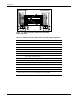
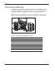
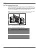
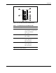
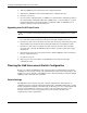
2. Slide the GbE Interconnect Switch into the right communication bay in the front side of
the ProLiant BL p-Class server blade enclosure (1).
3. Lock the ejector lever (2).
1
2
Figure 2-2: Installing the GbE Interconnect Switches
4. Repeat steps 2 and 3 for the second GbE Interconnect Switch in the left
communication bay.
IMPORTANT: Be sure that the interconnect modules are fully seated. The latch/handle will drop
into place when the module is firmly seated.
Replacing an Existing GbE Interconnect Switch
CAUTION: Removing an RJ-45 Patch Panel from a powered enclosure will result in the loss
of network communications between the server blade and the network infrastructure.
IMPORTANT: If you are replacing an existing GbE Interconnect Switch or upgrading from an RJ-45
Patch Panel, and have strict security requirements:
• Do not cable the GbE Interconnect Switch until after configuration.
Or
• Connect the GbE Interconnect Switch to the optional Diagnostic Station. The Diagnostic Station
enables you to power up, configure, and diagnose a ProLiant p-Class server blade or a ProLiant
p-Class GbE Interconnect Switch outside of the rack environment.
To replace an existing GbE Interconnect Switch:
1. If possible, save the configuration file to a TFTP server for later retrieval. Refer to the
“Saving Settings to a TFTP Server” section in Chapter 3 (console management interface)
and “Saving Settings to TFTP Server” in Chapter 4 (Web-based management interface).
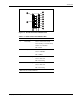
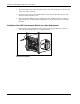
2. On the front side of the ProLiant BL p-Class server blade, release the ejector lever for the
GbE Interconnect Switch.
3. Pull down on the ejector lever to unlock the GbE Interconnect Switch from the enclosure.