HP ProLiant ML350 G6 Server User Guide Part Number 513503-002 March 2010 (Second Edition)
© Copyright 2009, 2010 Hewlett-Packard Development Company, L.P. The information contained herein is subject to change without notice. The only warranties for HP products and services are set forth in the express warranty statements accompanying such products and services. Nothing herein should be construed as constituting an additional warranty. HP shall not be liable for technical or editorial errors or omissions contained herein. Microsoft, Windows, and Windows Server are U.S.
Contents Component identification ............................................................................................................... 7 Front panel components ................................................................................................................................ 7 Front panel LEDs and buttons ......................................................................................................................... 8 Rear panel components ...................................
Hardware options installation....................................................................................................... 39 Introduction ............................................................................................................................................... 39 Processor option......................................................................................................................................... 39 Memory options ............................................
Redundant ROM support ................................................................................................................... 98 USB support and functionality ............................................................................................................ 99 Internal SD support ........................................................................................................................... 99 Diagnostic tools .................................................................
Battery replacement notice ........................................................................................................................ 124 Taiwan battery recycling notice ................................................................................................................. 125 Power cord statement for Japan ................................................................................................................. 125 Acoustics statement for Germany (Geräuschemission) ..........
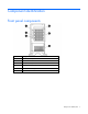
Component identification Front panel components Item Description 1 Power On/Standby button 2 UID button 3 USB connectors (2) 4 Hot-plug hard drive bays (8-bay SFF drive cage model) 5 Removable media bays 6 Optical drive Component identification 7
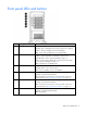
Front panel LEDs and buttons Item Description Status 1 System power LED Green = Power on Flashing green = Waiting for power due to group power capping Amber = System in standby, but power still applied Off = Power cord not attached or power supply failure 2 Health LED Green = Normal Amber = System degraded. To identify the component in a degraded state, see the system board LEDs (on page 13). Red = System critical.
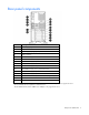
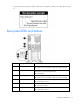
Rear panel components Item Description 1 Power supply bay 2 2 Keyboard connector 3 Power supply bay 1 (populated) 4 Video connector 5 USB connectors (2) 6 RJ-45 Ethernet connectors (2) 7 Slot 1 PCIe2 x8 (4, 2, 1)¹ 8 Slot 2 PCIe2 x8 (4, 2, 1)² 9 Slot 3 PCIe2 x8 (8, 4, 2, 1)³ 10 Slot 4 PCIe2 x16 (8, 4, 2, 1) 75W +EXT 75W4 11 Slot 5 PCIe2 x8 (4, 2, 1) 12 Slot 6 PCIe2 x8 (4, 2, 1) 13 RJ-45 Ethernet connector (dedicated iLO 2 management) 14 Serial connector 15 Mouse connector ¹Th
To support options beyond 75W, install the 150W PCIe video/graphics controller power cable option (on page 82). 4 Rear panel LEDs and buttons Item Description Status 1 Power supply 2 LED Green = Power supply is on and functioning. Off = AC power is not available or AC power supply has failed. 2 UID LED Blue = Activated Flashing blue = System managed remotely Off = Deactivated 3 Power supply 1 LED Green = Power supply is on and functioning.
Item Description Status 7 NIC 2 activity LED Green or flashing = Network activity Off = No network activity 8 NIC 1 link LED Green = Linked to network Off = Not linked to network 9 NIC 1 activity LED Green or flashing = Network activity Off = No network activity System board components Item Description 1 Processor 1 DIMM slots 2 Power supply backplane connector 3 Processor socket 2 4 System fan 4 connector 5 System power connectors 6 Processor 2 DIMM slots 7 System fan 3 connecto
Item Description 10 Front panel LED board connector 11 SAS connector B 12 SAS connector A 13 HP Smart Array P410i memory connector 14 TPM connector 15 SATA connectors (6) 16 Slot 1 PCIe2 x8 (4, 2, 1)¹ 17 Slot 2 PCIe2 x8 (4, 2, 1)² 18 10Gb sideband connector (MII 24-pin) 19 Slot 3 PCIe2 x8 (8, 4, 2, 1)³ 20 Slot 4 PCIe2 x16 (8, 4, 2, 1) 75W +EXT 75W4 21 Slot 5 PCIe2 x8 (4, 2, 1) 22 Slot 6 PCIe2 x8 (4, 2, 1) 23 Internal USB connector 24 Internal USB tape connector 25 System bat
System board LEDs Item Description Status 1 Power supply 1 Amber = No AC power or failed power supply Off = Power supply is on and functioning. 2 Power supply 2 Amber = No AC power or failed power supply Off = Power supply is on and functioning. 3 Processor 2 Amber = Processor 2 failed. Off = Processor 2 is functioning. 4 System fan 4 Amber = Fan is missing or has failed. Off = Fan is functioning. 5 AMP status Green = AMP mode is enabled.
Item Description Status 9 System fan 2 Amber = Fan is missing or has failed. Off = Fan is functioning. 10 Processor 1 Amber = Processor 1 failed. Off = Processor 1 is functioning. 11 System fan 1 Amber = Fan is missing or has failed. Off = Fan is functioning. 12 Processor 1 DIMMs Amber = An error has occurred. Off = Normal operation NMI functionality An NMI crash dump enables administrators to create crash dump files when a system is hung and not responding to traditional debug mechanisms.
Position Default Function S6 Off Off = No function On = Clear NVRAM S7 — Reserved S8 — Reserved S9 — Reserved S10 — Reserved When the system maintenance switch position 6 is set to the On position, the system is prepared to erase all system configuration settings from both CMOS and NVRAM. CAUTION: Clearing CMOS and/or NVRAM deletes configuration information. Be sure to properly configure the server or data loss could occur.
• SFF configuration with a second SAS controller • LFF configuration Component identification 16
SAS and SATA hard drive LEDs Item Description 1 Fault/UID LED (amber/blue) 2 Online LED (green) SAS and SATA hard drive LED combinations Online/activity LED (green) Fault/UID LED (amber/blue) Interpretation On, off, or flashing Alternating amber and blue The drive has failed, or a predictive failure alert has been received for this drive; it also has been selected by a management application.
Online/activity LED (green) Fault/UID LED (amber/blue) Interpretation Flashing irregularly Off The drive is active, and it is operating normally. Off Steadily amber A critical fault condition has been identified for this drive, and the controller has placed it offline. Replace the drive as soon as possible. Off Amber, flashing regularly (1 Hz) A predictive failure alert has been received for this drive. Replace the drive as soon as possible.
LED3 pattern LED4 pattern Interpretation — One blink every two seconds The system is powered down, and the cache contains data that has not yet been written to the drives. Restore system power as soon as possible to prevent data loss. Data preservation time is extended any time that 3.3 V auxiliary power is available, as indicated by LED 2. In the absence of auxiliary power, battery power alone preserves the data. A fullycharged battery can normally preserve data for at least two days.
FBWC module LEDs The FBWC module has two single-color LEDs (green and amber). The LEDs are duplicated on the reverse side of the cache module to facilitate status viewing. Green LED Amber LED Interpretation Off On A backup is in progress. Flashing (1 Hz) On A restore is in progress. Flashing (1 Hz) Off The capacitor pack is charging. On Off The capacitor pack has completed charging.
• Fan locations Item Description 1 Rear fan 1 2 Rear fan 2 3 Front fan 3 4 Front fan 4 • Single-processor, standard fan configuration Item Description 1 Rear fan 1 2 Rear fan 2 3 Front fan 3 Component identification 21
Item Description 4 Processor 1 5 DIMM baffle • Single-processor, redundant fan configuration Item Description 1 Rear fan 1 2 Rear fan 2 3 Front fan 3 4 Front fan 4 5 Processor 1 6 DIMM baffle 7 Large redundant fan air baffle Component identification 22
• Dual-processor, non-redundant fan configuration Item Description 1 Rear fan 1 2 Rear fan 2 3 Front fan 3 4 Processor 1 5 Processor 2 6 DIMM baffles • Dual-processor, redundant fan configuration Item Description 1 Rear fan 1 2 Rear fan 2 Component identification 23
Item Description 3 Front fan 3 4 Front fan 4 5 Processor 1 6 Processor 2 7 DIMM baffles 8 Large redundant fan air baffle Component identification 24
Operations Power up the server To power up the server, press the Power On/Standby button. To determine status, see "Front panel LEDs and buttons (on page 8)." Power down the server WARNING: To reduce the risk of personal injury, electric shock, or damage to the equipment, remove the power cord to remove power from the server. The front panel Power On/Standby button does not completely shut off system power. Portions of the power supply and some internal circuitry remain active until AC power is removed.
3. After performing the installation or maintenance procedure, press the rail-release latches and slide the server back into the rack. Remove the server from the rack To remove the server from an HP, telco, or third-party rack: 1. Power down the server (on page 25). 2. Disconnect the cabling. 3. Extend the server from the rack (on page 25). Reverse the server installation steps in the documentation that ships with the rack-mounting option. 4. Remove the server from the rack. 5.
For operations involving removable media bay access, the media bay panel can be removed from the bezel. Remove the access panel 1. Release the access panel latch. 2. Slide the access panel back about 1.5 cm (0.5 in). 3. Lift and remove the access panel. CAUTION: For proper cooling, do not operate the server without the access panel, baffles, expansion slot covers, hard drives, or blanks installed.
Install the access panel 1. Place the access panel on top of the server, allowing it to extend past the rear of the server approximately 1.5 cm (0.5 in). 2. Slide the access panel forward until it clicks into place, and close the access panel latch. Remove the media bay blank 1. Power down the server (on page 25). 2. Do one of the following: o Open or remove the tower bezel, as needed ("Open or remove the tower bezel" on page 26). o Extend the server from the rack (on page 25).
4. Remove the large redundant fan air baffle. Remove the DIMM baffle 1. Power down the server (on page 25). 2. Do one of the following: o Open or remove the tower bezel, as needed ("Open or remove the tower bezel" on page 26). o Extend the server from the rack (on page 25). 3. Remove the access panel (on page 27). 4. Remove the large redundant fan air baffle, if installed ("Remove the large redundant fan air baffle" on page 28). 5. Remove the DIMM baffle.
Remove a fan blank 1. Power down the server (on page 25). 2. Do one of the following: o Open or remove the tower bezel, as needed ("Open or remove the tower bezel" on page 26). o Extend the server from the rack (on page 25). 3. Remove the access panel (on page 27). 4. Remove the large redundant fan air baffle, if installed ("Remove the large redundant fan air baffle" on page 28). 5. Remove the fan blank.
Setup Optional installation services Delivered by experienced, certified engineers, HP Care Pack services help you keep your servers up and running with support packages tailored specifically for HP ProLiant systems. HP Care Packs let you integrate both hardware and software support into a single package. A number of service level options are available to meet your needs.
In a tower configuration, leave at least a 7.6-cm (3-in) clearance space at the front and back of the server for proper ventilation. Rack server To allow for servicing and adequate airflow, observe the following space and airflow requirements when deciding where to install a rack: • Leave a minimum clearance of 63.5 cm (25 in) in front of the rack. • Leave a minimum clearance of 76.2 cm (30 in) behind the rack. • Leave a minimum clearance of 121.
CAUTION: To reduce the risk of damage to the equipment when installing third-party options: • Do not permit optional equipment to impede airflow around the server or to increase the internal rack temperature beyond the maximum allowable limits. • Do not exceed the manufacturer’s TMRA. Power requirements Installation of this equipment must comply with local and regional electrical regulations governing the installation of information technology equipment by licensed electricians.
Rack planning resources The rack resource kit ships with all HP branded or Compaq branded 9000, 10000, and H9 series racks. For more information on the content of each resource, refer to the rack resource kit documentation. If you intend to deploy and configure multiple servers in a single rack, refer to the white paper on highdensity deployment at the HP website (http://www.hp.com/products/servers/platforms).
Contents of the rack server shipping carton Unpack the server shipping carton and locate the materials and documentation necessary for installing the server. All the rack mounting hardware necessary for installing the server into the rack is included with the rack or the server.
2. Return the server to an upright position. 3. Connect peripheral devices to the server ("Rear panel components" on page 9). WARNING: To reduce the risk of electric shock, fire, or damage to the equipment, do not plug telephone or telecommunications connectors into RJ-45 connectors. 4. Connect the power cord to the rear of the server. 5. Connect the power cord to the AC power source.
2. Install an additional extender bracket (included with the server) to the cable management arm. Refer to "Converting the cable management arm swing" in the installation instructions that ship with the 37U Quick Deploy Rail System. 3. Connect peripheral devices to the server ("Rear panel components" on page 9). 4. Connect the power cord to the rear of the server. 5. Connect the power cord to the AC power source.
• Manual installation—Insert the operating system CD into the CD-ROM drive and reboot the server. This process may require you to obtain additional drivers from the HP website (http://www.hp.com/support). Follow the on-screen instructions to begin the installation process. For information on using these installation paths, refer to the SmartStart installation poster in the HP ProLiant Essentials Foundation Pack, included with the server.
Hardware options installation Introduction If more than one option is being installed, read the installation instructions for all the hardware options and identify similar steps to streamline the installation process. WARNING: To reduce the risk of personal injury from hot surfaces, allow the drives and the internal system components to cool before touching them. CAUTION: To prevent damage to electrical components, properly ground the server before beginning any installation procedure.
6. Place the tower server on its side. 7. Open the processor retaining latch and the processor socket retaining bracket. 8. Remove the processor socket protective cover. IMPORTANT: Be sure the processor remains inside the processor installation tool. 9. If the processor has separated from the installation tool, carefully re-insert the processor in the tool.
10. Align the processor installation tool with the socket and install the processor. 11. Press down firmly until the processor installation tool clicks and separates from the processor, and then remove the processor installation tool.
12. Close the processor socket retaining bracket and the processor retaining latch. 13. Open the heatsink locking levers.
14. Remove the heatsink protective cover. 15. Install the heatsink. 16. Close the heatsink locking levers. 17. (Optional) To optimize performance, install memory into the processor 2 DIMM slots ("System board components" on page 11). 18. Remove the fan blank in fan bay 3 ("Remove a fan blank" on page 30).
19. Install the fan into fan bay 3. 20. Connect the fan cable to the system board ("System board components" on page 11). 21. Install the DIMM baffle onto the fan. 22. Install the large redundant fan air baffle, if removed. 23. Install the access panel (on page 28). 24. Do one of the following: 25. o Close or install the tower bezel, as needed. o Slide the server back into the rack. Power up the server (on page 25).
IMPORTANT: This server does not support mixing RDIMMs and UDIMMs. Attempting to mix these two types causes the server to halt during BIOS initialization. The memory subsystem in this server can support RDIMMs or UDIMMs. Both types are referred to as DIMMs when the information applies to both types. When specified as RDIMM or UDIMM, the information applies to that type only. All memory installed in the server must be the same type.
Dual- and quad-rank DIMMs provide the greatest capacity with the existing memory technology. For example, if current DRAM technology supports 2-GB single-rank DIMMs, a dual-rank DIMM would be 4GB, and a quad-rank DIMM would be 8-GB. DIMM identification IMPORTANT: This server does not support mixing RDIMMs and UDIMMs. Attempting to mix these two types causes the server to halt during BIOS initialization.
• Advanced ECC—provides the greatest memory capacity for a given DIMM size, while providing up to 4-bit error correction. This mode is the default option for this server. • Mirrored Memory—provides maximum protection against failed DIMMs. Uncorrectable errors in one channel are corrected by the mirror channel. • Lockstep—provides enhanced protection while making all installed memory available to the operating system.
Advanced ECC memory configuration Advanced ECC memory is the default memory protection mode for this server. Standard ECC can correct single-bit memory errors and detect multi-bit memory errors. When multi-bit errors are detected using Standard ECC, the error is signaled to the server and causes the server to halt. Advanced ECC protects the server against some multi-bit memory errors.
• Each channel supports up to two Unbuffered DIMMs. • If quad-rank DIMMs are installed for a processor, a maximum of two DIMMs can be installed on each channel for that processor. • If a channel contains quad-rank DIMMs, the quad-rank DIMM must be installed first on that channel. DIMM speeds are supported as indicated in the following table.
Single-processor Mirrored Memory population order For Mirrored Memory mode configurations with a single processor, populate the DIMM slots in the following order: • • RDIMM o First: A and B o Next: D and E o Last: G and H o Do not populate slots C, F, or I. UDIMM o First: A and B o Last: D and E o Do not populate slots C, F, G, H, or I. After installing the DIMMs, use RBSU to configure the system for Mirrored Memory support ("Configuring mirrored memory" on page 93).
Single-processor Lockstep population order For Lockstep memory mode configurations with a single processor, populate the DIMM slots in the following order: • • RDIMM o First: A and B o Next: D and E o Last: G and H o Do not populate slots C, F, or I. UDIMM o First: A and B o Last: D and E o Do not populate slots C, F, G, H, or I. After installing the DIMMs, use RBSU to configure the system for Lockstep memory support ("Configuring lockstep memory" on page 94).
4. Remove the large redundant fan air baffle, if installed ("Remove the large redundant fan air baffle" on page 28). 5. Remove the DIMM baffle, if installed ("Remove the DIMM baffle" on page 29). 6. Remove a fan, if necessary. 7. Open the DIMM slot latches. 8. Install the DIMM. 9. Install a fan, if removed. 10. Install the DIMM baffle. 11. Install the large redundant fan air baffle, if removed. 12. Install the access panel (on page 28). 13. Do one of the following: 14.
To install the component: 1. Remove the hard drive blank. 2. Open the release latch to prepare the drive for installation.
3. Install the hard drive. 4. Determine the status of the drive by observing the drive LEDs ("SAS and SATA hard drive LEDs" on page 17). 5. Resume normal server operations. Hard drive cage options HP does not support mixing SFF and LFF optional hard drive expansion cages. Installing a hard drive expansion cage power cable To install the component: 1. Power down the server (on page 25). 2.
5. Remove all expansion boards. 6. Remove the large redundant fan air baffle, if installed ("Remove the large redundant fan air baffle" on page 28). 7. Remove the DIMM baffles ("Remove the DIMM baffle" on page 29). 8. Remove all fans. 9. Loosen the two system board thumbscrews.
10. Using the system board tray handles, slide the tray forward and remove the system board. 11. Connect the power cable from the option kit to the power supply backplane. Be sure to thread the cables through the hole in the center wall. 12. Install the system board. 13. Tighten the thumbscrews. 14. Connect all cables to the system board. 15. Install all fans. 16. Install all DIMM baffles. 17. Install the large redundant fan air baffle, if removed. 18. Install all expansion boards.
Eight-bay SFF drive cage option Before installing the optional SFF hard drive cage, you must install an optional SAS controller. See the instructions that ship with the option. CAUTION: To avoid damage to the pin connectors, install only supported hard drive cages and components in HP ProLiant ML350 G6 Servers. For supported options, see the QuickSpecs at the HP website (http://www.hp.com/servers/proliantml350). To install the component: 1.
6. Install the SFF hard drive cage into the server. 7. Connect the power cable to the optional hard drive backplane.
8. Connect the SAS cables to the optional SAS controller or optional SAS expander. 9. Install any hard drives or blanks ("SAS or SATA hard drive option" on page 52). 10. Install the access panel (on page 28). 11. Do one of the following: 12. o Close or install the tower bezel, as needed. o Slide the server back into the rack. Power up the server (on page 25).
4. Extend the primary hard drive cage from the chassis. 5. Disconnect the existing SAS cable from the SAS connector labeled "4 and 5" on the primary drive cage. Retain the original SAS cable for future use. 6.
o The "2LFF" labeled connector to the optional hard drive cage 7. Thread the LED and SAS/SATA controller cables through the optional drive cage bay. 8. Slide the optional hard drive cage about three-fourths of the way into the bay, leaving room to connect cables at the back of the drive cage. 9.
o The "6LFF" labeled connector to the primary hard drive cage 10. Connect the remaining connector to SAS connector B on the system board ("System board components" on page 11). 11. Slide the optional hard drive cage fully into the bay until it clicks, and then install the screws. CAUTION: Always populate each media bay with either a device or a blank. Proper airflow can only be maintained when the bays are populated. Unpopulated drive bays can lead to improper cooling and thermal damage. 12.
To install a half-height or full-height media device: 1. Power down the server (on page 25). 2. Do one of the following: o Open or remove the tower bezel, as needed ("Open or remove the tower bezel" on page 26). o Extend the server from the rack (on page 25). 3. Remove the access panel (on page 27). 4. Remove the media bay blank (on page 28). 5. Install the guide screws ("Identifying guide screws" on page 62), if applicable. 6.
8. Slide the drive into the bay until it clicks. 9. When shipping a server with a full-height device installed, replace the front guide screw with a shipping screw ("Installing the full-height media device shipping screw" on page 64). 10. Install the access panel (on page 28). 11. Do one of the following: o Close or install the tower bezel, as needed. o Slide the server back into the rack.
4. Install the silver shipping screw into the full-height device. Redundant fan assembly option To install the component: 1. Power down the server (on page 25). 2. Do one of the following: o Open or remove the tower bezel, as needed ("Open or remove the tower bezel" on page 26). o Extend the server from the rack (on page 25). 3. Remove the access panel (on page 27). 4. Remove the fan blank from fan bay 4 ("Remove a fan blank" on page 30). 5. Install the fan in fan bay 4. 6.
7. Align the baffle guide posts with the holes on the fan and the system board. 8. Install the large air baffle. 9. Install the access panel (on page 28). 10. Do one of the following: 11. o Close or install the tower bezel, as needed. o Slide the server back into the rack. Power up the server (on page 25). Redundant hot-plug power supply option The server supports a second hot-plug power supply to provide redundant power to the system if the primary power supply fails.
WARNING: To reduce the risk of electric shock or damage to the equipment: • Do not disable the power cord grounding plug. The grounding plug is an important safety feature. • Plug the power cord into a grounded (earthed) electrical outlet that is easily accessible at all times. • Unplug the power cord from the power supply to disconnect power to the equipment. • Do not route the power cord where it can be walked on or pinched by items placed against it.
CAUTION: Electrostatic discharge (ESD) can damage electronic components. Be sure that you are properly grounded (earthed) before beginning any installation procedure. To install the component: 1. Identify the redundant power supply bay ("Rear panel components" on page 9). IMPORTANT: Power supplies for the model shown are hot-pluggable. When using the redundant power supply option, it is not necessary to power down the server before removing or installing a power supply. 2. Remove the power supply blank.
6. Connect the power cord to the AC power source. 7. Be sure that the power supply LED is illuminated green ("Rear panel LEDs and buttons" on page 10). Expansion board options The server supports PCI, PCI-X, and PCI Express expansion boards. Removing the expansion slot cover To install the component: 1. Power down the server (on page 25). 2. Do one of the following: o Open or remove the tower bezel, as needed ("Open or remove the tower bezel" on page 26).
5. Remove the expansion slot cover. CAUTION: To prevent improper cooling and thermal damage, do not operate the server unless all PCI slots have either an expansion slot cover or an expansion board installed. Installing an expansion board When installing a high-wattage video/graphics controller, observe the following guidelines: • Install the controller in the x16 slot ("System board components" on page 11).
5. Install the expansion board. 6. Close the expansion slot latch to secure the board. 7. Connect any required internal cables to the expansion board. Refer to the documentation that ships with the expansion board. 8. Close the expansion board retainer. 9. Install the access panel (on page 28). 10. Do one of the following: 11. o Close or install the tower bezel, as needed. o Slide the server back into the rack. Connect any required external cables to the expansion board.
4. Remove the two T-10 screws from the rear panel, and then remove the rear access panel. Retain the screws for securing the PCI-X expansion cage. 5. Remove the airflow shield from the chassis. Retain the shield for future use if the PCI-X expansion cage is not installed.
6. Remove the four T-15 screws from the hard drive cage, and then partially extend the hard drive cage from the chassis. 7. Pull the spring-loaded locking pin out, and then turn it one-quarter turn to an extended position.
8. Remove a PCI-X expansion slot cover. 9. Install PCI-X expansion boards in the PCI-X expansion cage.
10. Install the PCI-X expansion cage. Secure the assembly with the screws from the rear access panel. 11. Turn the spring-loaded locking pin until it locks into the chassis. 12. Open the expansion board retainer. 13. Remove the expansion board or the expansion slot cover for expansion slot 1 ("Removing the expansion slot cover" on page 69). The PCI-X expansion cage is supported only by slot 1. 14. Install the included PCI Express conversion card into expansion slot 1.
With the PCI-X expansion cage option, the additional PCI-X slots are recognized as slot 1 by the ROM. 15. Close the expansion board retainer. 16. Connect the signal cable to the installed PCI Express conversion card and to the PCI-X expansion cage. 17. Disconnect the first power connector of both system power cables from any installed media bay devices. 18. Connect the included power cable extension: a. Connect the extension to the PCI-X expansion cage.
b. Connect the extension to the first power connector of both system power cables. 19. Connect the power connectors on the power cable extension to any installed media bay devices. Route the unused portion of the system power cables to avoid airflow restriction. 20. Install any other expansion boards ("Installing an expansion board" on page 70). 21. Slide the hard drive cage back into the chassis, and then secure the cage with the four T-15 screws. 22. Install the access panel (on page 28). 23.
o Install the server in the rack. 24. Connect any external cables to the PCI-X expansion boards. 25. Power up the server (on page 25).
6. Install the cache module. 7. Connect the cable to the cache module. 8. Connect the cable to the battery pack. 9. Install the battery pack. IMPORTANT: The server supports only one battery pack in the chassis. If more than one battery is needed, use the Velcro strips provided in the option kit to attach additional battery packs.
10. Install the access panel (on page 28). 11. Do one of the following: 12. o Close or install the tower bezel, as needed. o Slide the server back into the rack. Power up the server (on page 25). For more information, see the documentation that ships with the option. FBWC module and capacitor pack option CAUTION: Do not use this controller with cache modules designed for other controller models, because the controller can malfunction and you can lose data.
7. Install the FBWC module. 8. Connect the cable. 9. Install the capacitor pack. 10. Install the large redundant air baffle, if removed.
11. Install the access panel. 12. Do one of the following: 13. o Close or install the tower bezel, as needed. o Slide the server back into the rack. Power up the server (on page 25). 150W PCIe video/graphics controller power cable option To determine power requirements for supported options, use the power calculator located at the HP website (http://www.hp.com/servers/powercalculator). Before installing a high-wattage video/graphics controller, install the cable.
7. Remove the DIMM baffles ("Remove the DIMM baffle" on page 29). 8. Remove all fans. 9. Loosen the two system board thumbscrews. 10. Using the system board tray handles, slide the tray forward and remove the system board.
11. Connect the 10-pin connector on the PCIe power cable to the power supply backplane. Be sure to thread the cable through the center wall. 12. Install the system board. 13. Tighten the thumbscrews. 14. Connect all cables to the system board. 15. Install all fans. 16. Install all DIMM baffles. 17. Install the large redundant fan air baffle, if removed. 18. Install all expansion boards. 19. Connect the PCIe power cable to an installed PCIe expansion board, as needed.
• Do not remove an installed TPM. Once installed, the TPM becomes a permanent part of the system board. • When installing or replacing hardware, HP service providers cannot enable the TPM or the encryption technology. For security reasons, only the customer can enable these features. • When returning a system board for service replacement, do not remove the TPM from the system board. When requested, HP Service provides a TPM with the spare system board.
5. Install the TPM board. Press down on the connector to seat the board ("System board components" on page 11). 6. Install the TPM security rivet by pressing the rivet firmly into the system board. 7. Install the access panel (on page 28). 8. Do one of the following: 9. o Close or install the tower bezel, as needed. o Slide the server back into the rack. Power up the server (on page 25).
To help ensure maximum security, observe the following guidelines when retaining the recovery key/password: • Always store the recovery key/password in multiple locations. • Always store copies of the recovery key/password away from the server. • Do not save the recovery key/password on the encrypted hard drive. Enabling the Trusted Platform Module 1. When prompted during the start-up sequence, access RBSU by pressing the F9 key. 2. From the Main Menu, select Server Security. 3.
2. Disconnect all rear panel cabling ("Rear panel components" on page 9). 3. Remove the tower bezel ("Open or remove the tower bezel" on page 26). 4. Remove the feet. 5. Remove both tower configuration panels: a. Using the T-10 Torx screwdriver, remove the front panel screws. b. Unhook the tower configuration panels from the chassis.
c. Slide them back and away from the chassis.
6. Install the foot blanks. 7. Remove the access panel (on page 27). 8. Align the pins on the rack bezel with the corresponding slots on the chassis. Secure the rack bezel to the chassis using the screws inside the chassis. 9. Install the access panel (on page 28). 10. Install the server into the rack ("Installing the server into the rack" on page 36).
Configuration and utilities Configuration tools SmartStart software SmartStart is a collection of software that optimizes single-server setup, providing a simple and consistent way to deploy server configuration. SmartStart has been tested on many ProLiant server products, resulting in proven, reliable configurations.
variables to determine the configuration and then writes the results to an editable script file. This file can then be deployed across multiple servers with similar hardware and software components. For more information, refer to the SmartStart Scripting Toolkit User Guide on the HP website (http://h18004.www1.hp.com/products/servers/management/toolkit/documentation.html).
NOTE: If the boot drive is not empty or has been written to in the past, ORCA does not automatically configure the array. You must run ORCA to configure the array settings. Drives installed Drives used RAID level 1 1 RAID 0 2 2 RAID 1 3, 4, 5, or 6 3, 4, 5, or 6 RAID 5 More than 6 0 None To change any ORCA default settings and override the auto-configuration process, press the F8 key when prompted. By default, the auto-configuration process configures the system for the English language.
7. Press the Esc key to exit the current menu or press the F10 key to exit RBSU. For more information on mirrored memory, see the white paper on the HP website (http://h18000.www1.hp.com/products/servers/technology/memoryprotection.html). Configuring online spare memory To configure online spare memory: 1. Install the required DIMMs ("Installing DIMMs" on page 51). 2. Access RBSU by pressing the F9 key during power-up when the prompt is displayed in the upper right corner of the screen. 3.
• Beginning with ACU version 8.28.13.0, provides diagnostic functionality on the Diagnostics tab (formerly known as Array Diagnostics Utility). For optimum performance, the minimum display settings are 1024 × 768 resolution and 16-bit color. Servers running Microsoft® operating systems require one of the following supported browsers: • Internet Explorer 6.0 or later • Mozilla Firefox 2.0 or later For Linux servers, see the README.TXT file for additional browser and support information.
WARNING! WARNING! WARNING! The serial number is loaded into the system during the manufacturing process and should NOT be modified. This option should only be used by qualified service personnel. This value should always match the serial number sticker located on the chassis. Warning: The serial number should ONLY be modified by qualified personnel. This value should always match the serial number located on the chassis. 5. Press the Enter key to clear the warning. 6.
Integrated Lights-Out 2 technology The iLO 2 subsystem is a standard component of selected ProLiant servers that provides server health and remote server manageability. The iLO 2 subsystem includes an intelligent microprocessor, secure memory, and a dedicated network interface. This design makes iLO 2 independent of the host server and its operating system. The iLO 2 subsystem provides remote access to any authorized network client, sends alerts, and provides other server management functions.
IMPORTANT: You must install and use HP SIM to benefit from the Pre-Failure Warranty for processors, SAS and SATA hard drives, and memory modules. For additional information, refer to the Management CD in the HP ProLiant Essentials Foundation Pack or the HP SIM website (http://www.hp.com/go/hpsim). Management Agents Management Agents provide the information to enable fault, performance, and configuration management.
USB support and functionality USB support HP provides both standard USB support and legacy USB support. Standard support is provided by the OS through the appropriate USB device drivers. Before the OS loads, HP provides support for USB devices through legacy USB support, which is enabled by default in the system ROM. Legacy USB support provides USB functionality in environments where USB support is not available normally.
HP Insight Diagnostics Online Edition is a web-based application that captures system configuration and other related data needed for effective server management. Available in Microsoft® Windows® and Linux versions, the utility helps to ensure proper system operation. For more information or to download the utility, refer to the HP website (http://www.hp.com/servers/diags).
Remote support and analysis tools HP Insight Remote Support software HP Insight Remote Support software delivers secure remote support for your HP Servers and Storage, 24 X 7, so you can spend less time solving problems and more time focused on your business. You can have your systems remotely monitored for hardware failure using secure technology that has been proven at thousands of companies around the world. In many cases, you can avoid problems before they occur.
IMPORTANT: Always perform a backup before installing or updating device drivers. ProLiant Support Packs PSPs represent operating system-specific bundles of ProLiant optimized drivers, utilities, and management agents. Refer to the PSP website (http://h18000.www1.hp.com/products/servers/management/psp.html). Operating system version support Refer to the operating system support matrix (http://www.hp.com/go/supportos).
Troubleshooting Troubleshooting resources The HP ProLiant Servers Troubleshooting Guide provides procedures for resolving common problems and comprehensive courses of action for fault isolation and identification, error message interpretation, issue resolution, and software maintenance on ProLiant servers and server blades. This guide includes problemspecific flowcharts to help you navigate complex troubleshooting processes. To view the guide, select a language: • English (http://www.hp.
Symbols on equipment The following symbols may be placed on equipment to indicate the presence of potentially hazardous conditions. This symbol indicates the presence of hazardous energy circuits or electric shock hazards. Refer all servicing to qualified personnel. WARNING: To reduce the risk of injury from electric shock hazards, do not open this enclosure. Refer all maintenance, upgrades, and servicing to qualified personnel. This symbol indicates the presence of electric shock hazards.
WARNING: To reduce the risk of electric shock or damage to the equipment: • Do not disable the power cord grounding plug. The grounding plug is an important safety feature. • Plug the power cord into a grounded (earthed) electrical outlet that is easily accessible at all times. • Unplug the power cord from the power supply to disconnect power to the equipment. • Do not route the power cord where it can be walked on or pinched by items placed against it.
Prepare the server for diagnosis 1. Be sure the server is in the proper operating environment with adequate power, air conditioning, and humidity control. For required environmental conditions, see the server documentation. 2. Record any error messages displayed by the system. 3. Remove all diskettes, CD-ROMs, DVD-ROMs, and USB drive keys. 4. Power down the server and peripheral devices if you will be diagnosing the server offline. If possible, always perform an orderly shutdown: a.
Service notifications To view the latest service notifications, refer to the HP website (http://www.hp.com/go/bizsupport). Select the appropriate server model, and then click the Troubleshoot a Problem link on the product page. Troubleshooting flowcharts To effectively troubleshoot a problem, HP recommends that you start with the first flowchart in this section, "Start diagnosis flowchart (on page 107)," and follow the appropriate diagnostic path.
General diagnosis flowchart The General diagnosis flowchart provides a generic approach to troubleshooting. If you are unsure of the problem, or if the other flowcharts do not fix the problem, use the following flowchart. Item Refer to 1 "Symptom information (on page 105)" 2 "Loose connections (on page 106)" 3 "Service notifications (on page 107)" 4 The most recent version of a particular server or option firmware is available on the HP Support website (http://www.hp.com/support).
Item Refer to 5 "General memory problems are occurring" in the HP ProLiant Servers Troubleshooting Guide located on the Documentation CD or on the HP website (http://www.hp.com/support) 6 Server maintenance and service guide, located on the Documentation CD or the HP website (http://www.hp.com/products/servers/platforms) 7 • Server maintenance and service guide, located on the Documentation CD or the HP website (http://www.hp.
Server power-on problems flowchart Symptoms: • The server does not power on. • The system power LED is off or amber.
• The external health LED is red or amber. • The internal health LED is red or amber. NOTE: For the location of server LEDs and information on their statuses, refer to the server documentation.
Troubleshooting 112
POST problems flowchart Symptoms: • Server does not complete POST NOTE: The server has completed POST when the system attempts to access the boot device.
Item Refer to OS boot problems flowchart Symptoms: • Server does not boot a previously installed operating system Troubleshooting 114
• Server does not boot SmartStart Possible causes: • Corrupted operating system • Hard drive subsystem problem • Incorrect boot order setting in RBSU Item Refer to 1 HP ROM-Based Setup Utility User Guide (http://www.hp.com/servers/smartstart) 2 "POST problems flowchart (on page 113)" 3 • "Hard drive problems" in the HP ProLiant Servers Troubleshooting Guide located on the Documentation CD or on the HP website (http://www.hp.
Server fault indications flowchart Symptoms: • Server boots, but a fault event is reported by Insight Management Agents (on page 98) • Server boots, but the internal health LED, external health LED, or component health LED is red or amber Troubleshooting 116
NOTE: For the location of server LEDs and information on their statuses, refer to the server documentation. Possible causes: • Improperly seated or faulty internal or external component • Unsupported component installed • Redundancy failure • System overtemperature condition Item Refer to 1 "Management agents (on page 98)" or in the HP ProLiant Servers Troubleshooting Guide located on the Documentation CD or on the HP website (http://www.hp.
POST error messages and beep codes For a complete listing of error messages, refer to the "POST error messages" in the HP ProLiant Servers Troubleshooting Guide located on the Documentation CD or on the HP website (http://www.hp.com/support). WARNING: To avoid potential problems, ALWAYS read the warnings and cautionary information in the server documentation before removing, replacing, reseating, or modifying system components.
Battery replacement If the server no longer automatically displays the correct date and time, you may need to replace the battery that provides power to the real-time clock. Under normal use, battery life is 5 to 10 years. WARNING: The computer contains an internal lithium manganese dioxide, a vanadium pentoxide, or an alkaline battery pack. A risk of fire and burns exists if the battery pack is not properly handled. To reduce the risk of personal injury: • Do not attempt to recharge the battery.
Regulatory compliance notices Regulatory compliance identification numbers For the purpose of regulatory compliance certifications and identification, this product has been assigned a unique regulatory model number. The regulatory model number can be found on the product nameplate label, along with all required approval markings and information. When requesting compliance information for this product, always refer to this regulatory model number.
to radio communications. However, there is no guarantee that interference will not occur in a particular installation. If this equipment does cause harmful interference to radio or television reception, which can be determined by turning the equipment off and on, the user is encouraged to try to correct the interference by one or more of the following measures: • Reorient or relocate the receiving antenna. • Increase the separation between the equipment and receiver.
Canadian notice (Avis Canadien) Class A equipment This Class A digital apparatus meets all requirements of the Canadian Interference-Causing Equipment Regulations. Cet appareil numérique de la classe A respecte toutes les exigences du Règlement sur le matériel brouilleur du Canada. Class B equipment This Class B digital apparatus meets all requirements of the Canadian Interference-Causing Equipment Regulations.
This symbol on the product or on its packaging indicates that this product must not be disposed of with your other household waste. Instead, it is your responsibility to dispose of your waste equipment by handing it over to a designated collection point for the recycling of waste electrical and electronic equipment.
Korean notice Class A equipment Class B equipment Chinese notice Class A equipment Laser compliance This product may be provided with an optical storage device (that is, CD or DVD drive) and/or fiber optic transceiver. Each of these devices contains a laser that is classified as a Class 1 Laser Product in accordance with US FDA regulations and the IEC 60825-1. The product does not emit hazardous laser radiation. Each laser product complies with 21 CFR 1040.10 and 1040.
WARNING: The computer contains an internal lithium manganese dioxide, a vanadium pentoxide, or an alkaline battery pack. A risk of fire and burns exists if the battery pack is not properly handled. To reduce the risk of personal injury: • Do not attempt to recharge the battery. • Do not expose the battery to temperatures higher than 60°C (140°F). • Do not disassemble, crush, puncture, short external contacts, or dispose of in fire or water.
Electrostatic discharge Preventing electrostatic discharge To prevent damaging the system, be aware of the precautions you need to follow when setting up the system or handling parts. A discharge of static electricity from a finger or other conductor may damage system boards or other static-sensitive devices. This type of damage may reduce the life expectancy of the device. To prevent electrostatic damage: • Avoid hand contact by transporting and storing products in static-safe containers.
Server specifications Environmental specifications Specification Value Temperature range* Operating 10°C to 35°C (50°F to 95°F) Shipping -40°C to 70°C (-40°F to 158°F) Maximum wet bulb temperature 28°C (82.4°F) Relative humidity (noncondensing)** Operating 10% to 90% Non-operating 5% to 95% * All temperature ratings shown are for sea level. An altitude derating of 1°C per 300 m (1.8°F per 1,000 ft) to 3048 m (10,000 ft) is applicable. No direct sunlight allowed.
Rated input current 10 A at 100 VAC 4.
Rated input frequency 50 Hz to 60 Hz Rated input current 5.5 A at 100 VAC 2.
Technical support Before you contact HP Be sure to have the following information available before you call HP: • Technical support registration number (if applicable) • Product serial number • Product model name and number • Product identification number • Applicable error messages • Add-on boards or hardware • Third-party hardware or software • Operating system type and revision level HP contact information For the name of the nearest HP authorized reseller: • See the Contact HP worldwi
• Optional—Parts for which customer self repair is optional. These parts are also designed for customer self repair. If, however, you require that HP replace them for you, there may or may not be additional charges, depending on the type of warranty service designated for your product. NOTE: Some HP parts are not designed for customer self repair. In order to satisfy the customer warranty, HP requires that an authorized service provider replace the part.
Pour plus d'informations sur le programme CSR de HP, contactez votre Mainteneur Agrée local. Pour plus d'informations sur ce programme en Amérique du Nord, consultez le site Web HP (http://www.hp.com/go/selfrepair). Riparazione da parte del cliente Per abbreviare i tempi di riparazione e garantire una maggiore flessibilità nella sostituzione di parti difettose, i prodotti HP sono realizzati con numerosi componenti che possono essere riparati direttamente dal cliente (CSR, Customer Self Repair).
HINWEIS: Einige Teile sind nicht für Customer Self Repair ausgelegt. Um den Garantieanspruch des Kunden zu erfüllen, muss das Teil von einem HP Servicepartner ersetzt werden. Im illustrierten Teilekatalog sind diese Teile mit „No“ bzw. „Nein“ gekennzeichnet. CSR-Teile werden abhängig von der Verfügbarkeit und vom Lieferziel am folgenden Geschäftstag geliefert. Für bestimmte Standorte ist eine Lieferung am selben Tag oder innerhalb von vier Stunden gegen einen Aufpreis verfügbar.
el caso de todas sustituciones que lleve a cabo el cliente, HP se hará cargo de todos los gastos de envío y devolución de componentes y escogerá la empresa de transporte que se utilice para dicho servicio. Para obtener más información acerca del programa de Reparaciones del propio cliente de HP, póngase en contacto con su proveedor de servicios local. Si está interesado en el programa para Norteamérica, visite la página web de HP siguiente (http://www.hp.com/go/selfrepair).
Opcional – Peças cujo reparo feito pelo cliente é opcional. Essas peças também são projetadas para o reparo feito pelo cliente. No entanto, se desejar que a HP as substitua, pode haver ou não a cobrança de taxa adicional, dependendo do tipo de serviço de garantia destinado ao produto. OBSERVAÇÃO: Algumas peças da HP não são projetadas para o reparo feito pelo cliente. A fim de cumprir a garantia do cliente, a HP exige que um técnico autorizado substitua a peça.
Technical support 136
Technical support 137
Acronyms and abbreviations ABEND abnormal end ACU Array Configuration Utility ADU Array Diagnostics Utility AMP Advanced Memory Protection ASR Automatic Server Recovery BBWC battery-backed write cache DDR double data rate FBWC flash-backed write cache IEC International Electrotechnical Commission iLO Integrated Lights-Out IML Integrated Management Log LFF large form-factor LV DIMM Low voltage DIMM Acronyms and abbreviations 138
NIC network interface controller NMI non-maskable interrupt ORCA Option ROM Configuration for Arrays PCI Express Peripheral Component Interconnect Express PCI-X peripheral component interconnect extended PDU power distribution unit POST Power-On Self Test PSP ProLiant Support Pack RBSU ROM-Based Setup Utility RDIMM Registered Dual In-line Memory Module SAS serial attached SCSI SATA serial ATA SFF small form-factor SIM Systems Insight Manager Acronyms and abbreviations 139
TMRA recommended ambient operating temperature TPM trusted platform module UDIMM Unregistered Dual In-Line Memory Module UID unit identification Acronyms and abbreviations 140
Index 1 150W PCIe video/graphics controller power cable option 82 A access panel 27, 28 accessing servers 26 acoustics statement for Germany 125 ACU (Array Configuration Utility) 94 adapter LEDs 7, 8, 10, 13 additional information 103 ADU (Array Diagnostic Utility) 100 air baffle 28, 29 airflow requirements 32 Altiris Deployment Solution 95 Altiris eXpress Deployment Server 95 Array Configuration Utility (ACU) 94 ASR (Automatic Server Recovery) 96 authorized reseller 130 auto-configuration process 92 Autom
F fan assembly 65 fan bay numbering 20 fan blank 30 fan configurations 20 fans 20 FBWC module 20, 80 FCC rating label 120 features 7 Federal Communications Commission (FCC) notice 120, 121 flowcharts 107, 108, 110, 113, 114, 116 front bezel 26 front panel components 7 front panel LEDs 8 full-height media device 62, 64 G general diagnosis flowchart 108 guide screws 62 H half-height media device 62 hard drive cage 54, 57, 59 hard drive LEDs 17 hard drives 17 hard drives, determining status of 17 hardware op
ORCA (Option ROM Configuration for Arrays) 95 OS boot problems flowchart 114 P PATA optical drive 62 PCI Express conversion card 71 PCI-X expansion cage 71 phone numbers 130 POST problems flowchart 113 power cables 54 power cabling, internal 54 power calculator 82 power cord 104, 125 power distribution unit (PDU) 33 power LEDs, system 7, 8, 13, 18 Power On/Standby button 7, 8, 25, 37 power requirements 33 power supplies 66, 67, 127 powering down 25 powering up 25, 92 power-on problems flowchart 110 pre-dia
Trusted Platform Module (TPM) 84, 85, 86 U UID LED 8, 10, 14, 25 updating the system ROM 98 USB support 99 utilities 91 utilities, deployment 91, 92, 95 V ventilation 31 video/graphics controller power cable 82 W warnings 34, 104 website, HP 130 Index 144