HP ProLiant SL Advanced Power Manager User Guide Abstract This guide provides installation and operation guidance for the HP ProLiant SL Advanced Power Manager. This guide is for the person who installs, administers, and troubleshoots servers and storage systems.
© Copyright 2009, 2012 Hewlett-Packard Development Company, L.P. The information contained herein is subject to change without notice. The only warranties for HP products and services are set forth in the express warranty statements accompanying such products and services. Nothing herein should be construed as constituting an additional warranty. HP shall not be liable for technical or editorial errors or omissions contained herein. Confidential computer software.
Contents Introduction .................................................................................................................................. 7 SL-APM overview....................................................................................................................................... 7 SL-APM front view ............................................................................................................................ 7 SL-APM rear view ..........................................
SL-APM and SL-APM Distribution Module cabling ........................................................................................ 31 Rack level power capping ........................................................................................................................ 31 Power baseline ............................................................................................................................. 31 Setting power capping ...........................................................
Troubleshooting .......................................................................................................................... 58 Alert messages ........................................................................................................................................ 58 Devices not discovered ............................................................................................................................ 58 Commands ......................................................
Show time .............................................................................................................................................. 70 Show power baseline .............................................................................................................................. 70 Show version .......................................................................................................................................... 71 Upgrade image .....................................
Introduction SL-APM overview SL-APM is a single point of contact for HP ProLiant Scalable System administration.
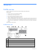
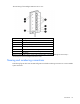
Item Description 7 PDM1 for HP Intelligent Modular PDU Extension Bar 8 PDM2 for HP Intelligent Modular PDU Extension Bar 9 SL-APM Distribution Module ports (see Caution below) 10 Network interface 100mb activity (amber) LED, indicates that the link is in 100Base-T mode and blinks when transmitting or receiving data. When the link is 10mb, the LED does not illuminate.
HP ProLiant SL Advanced Power Manager Distribution Module The distribution module includes a connector bay for the SL-APM and cables for SL Scalable Series servers.
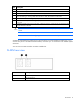
The total rating of the Intelligent Extension Bar is 16 A. Callout Description 1 Row of green power indicators (one for each outlet) 2 Row of blue UID indicators (one for each outlet) 3 2.4-m (8-ft) input power cord 4 Five managed 10 A, IEC-320 C13 outlets 5 Blue UID indicator for the Intelligent Extension Bar 6 Green power indicator for the Intelligent Extension Bar Reset button* 7 *When you press the Reset button, power to the managed outlets is maintained.
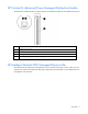
2U-chassis, DL2000 Scalable System Enclosure with four half-width 1U nodes Item Description 1 SL-APM 2 DL series enclosure 3 Bay 4 of a 2U-chassis, DL2000 Scalable System Enclosure with four half-width 1U nodes 2U-chassis, SL6000 Scalable System Enclosure with four 1U half-width nodes Item Description 1 SL-APM 2 SL-APM Distribution Module 3 SL series enclosure Introduction 11
Item Description 4 Bay 3 of a 2U-chassis, SL6000 Scalable System Enclosure with four 1U half-width nodes 4U-chassis, s6500 Scalable System Enclosure with eight 1U half-width nodes Item Description 1 SL-APM 2 SL-APM Distribution Module 3 SL series enclosure 4 Bay 4 of a 4U-chassis, s6500 Scalable System Enclosure with eight 1U half-width nodes Introduction 12
4U-chassis, s6500 Scalable System Enclosure with two 4U half-width nodes Item Description 1 SL-APM 2 SL-APM Distribution Module 3 SL series enclosure 4 Bay 1 of a 4U-chassis, s6500 Scalable System Enclosure with two 4U half-width nodes Introduction 13
4U-chassis, s6500 Scalable System Enclosure with four 2U half-width nodes Item Description 1 SL-APM 2 SL-APM Distribution Module 3 SL series enclosure 4 Bay 3 of a 4U-chassis, s6500 Scalable System Enclosure with four 2U half-width nodes When entering commands that require specific port and node numbers, use the SL-APM port number, SL-APM Distribution Module port number, and the SL server node number.
Installation and configuration Prerequisites for installation The SL-APM can be administered through the serial console. Initial configuration requires a serial terminal set to 115200. Preparing for installation 1. If you are not using a DHCP server, have your necessary IP address information available that will be used to access the SL-APM. 2. Secure a serial terminal, which is required for the initial setup of the SL-APM. 3.
• Enter the commands manually. This procedure is for advanced users who want more control over the configuration process. • Duplicate the configuration. For more information, see "Duplicating the configuration (on page 18)." Using the configuration wizard When you enter CONFIG, you are prompted to complete the following tasks. 1. Set the onboard clockIf you select Y, you will be prompted to enter: o MonthEnter a value between 1 to 12. Press Enter. o DayEnter a value between 1 to 31. Press Enter.
11. Save the new configuration. To save the new configuration, select Y. All settings relating to the SL-APM Ethernet and serial interfaces are persistent and stored in the SL-APM. Serial port configuration Verify that the client matches the following settings: • Baud rate115200 • Data bits8 • Stop bits1 • ParityNone • Flow controlNone To set a different serial baud rate, enter SET SERIAL , where is the baud rate setting to be used.
Verifying network communication To verify the network communication is working, enter PING , where is the IP address you want to test. Security configuration The network interface is disabled when password protection is removed. For more information about passwords, see "Working with passwords (on page 45)". Protocol configuration SL-APM supports SSH and Telnet. Working with SSH configuration To enable SSH access, enter ENABLE SSH. To disable SSH access, enter DISABLE SSH.
Command Line Interface Command line conventions CLI input is case insensitive except when otherwise noted. The CLI uses a simple, case insensitive verb noun "" syntax. Each command follows the conventions listed in the following table. Symbol Description Denotes the variable within the symbols that must be substituted with a value, such as a user name. Symbols must be removed. UPPER CASE Denotes input to be entered as shown. Unless noted, symbol is not case-sensitive.
2. When prompted, enter the assigned IP address or FQDN name of SL-APM. 3. Enter Administrator. 4. Enter a valid password. The CLI command prompt appears. 5. Enter commands for SL-APM. 6. To terminate the remote access Telnet session, close the communication software or enter EXIT, LOGOUT, or QUIT at the CLI command prompt. Accessing the SL-APM through the serial port You can also access the SL-APM through the serial port. For more information, see "Serial Port Configuration (on page 17).
7 : Compute node (active) 8 : Compute node (active) Power supply slot 1 is occupied, status good Power supply slot 2 is occupied, status good Power supply slot 3 is occupied, status good Power supply slot 4 is empty Fan slot 1 status good Fan slot 2 status good Fan slot 3 status good Fan slot 4 status good Fan slot 5 status good Fan slot 6 status good Fan slot 7 status good Fan slot 8 status good To show a particular rack, enter SHOW RACK, followed by either the SL-APM port or both the SL-APM and SL-APM Dis
1: enabled 2: enabled 3: enabled 4: enabled 5: enabled 6: enabled Input Feeds: 1: Amps Drawn Infeed Status Infeed Load Status 2: Amps Drawn Infeed Status Infeed Load Status 3: Amps Drawn Infeed Status Infeed Load Status 4: Amps Drawn Infeed Status Infeed Load Status : 0.840000 : On : Normal : 0.860000 : On : Normal : 0.800000 : On : Normal : 2.530000 : N/A : Normal This command produces the same results as the SHOW SERVERS and SHOW TOPOLOGY commands.
Serial #: USE119A2YW Serial #: USE119A2YT Serial #: USE119A319 Serial #: USE119A31C Serial #: USE119A2N8 Serial #: USE119A2N3 Serial #: USE119A2N4 Serial #: USE121AJYH 2 : Compute node (active) Asset tag: myserver2 3 : Compute node (active) Asset tag: myserver3 4 : Compute node (active) Asset tag: myserver4 5 : Compute node (active) Asset tag: myserver5 6 : Compute node (active) Asset tag: myserver6 7 : Compute node (active) Asset tag: myserver7 8 : Compute node (active) Asset tag: myserver8 Power supply s
Amps Drawn Infeed Status Infeed Load Status 4: Amps Drawn Infeed Status Infeed Load Status : 0.830000 : On : Normal : 2.590000 : On : Normal Showing the MAC address To show the MAC address, enter SHOW MACADDR. The MAC address appears. The MAC address information appears following each module listing. For example, the following text might appear on screen. SL-APM> show macaddr 1: Dist.
SL-APM logging Overview of logging Logging enables you to see the following information in SL-APM • Actions taken • Events • Time when the action was taken or event occurred SL-APM has the following types of logs: • Event logs, where SL-APM records events • Fault logs, where SL-APM records errors, such as a power supply not working SL-APM has the following types of fault log entries: o Normal errors, such as an invalid password o Alerts, in which the red LED illuminates.
003:WED JAN 13 11:03:20 004:WED JAN 13 11:03:29 005:WED JAN 13 11:03:33 006:WED JAN 13 11:04:19 were powered on 007:WED JAN 13 11:04:36 #1, port 5, slot 4 008:WED JAN 13 11:04:40 were powered off 009:WED JAN 13 11:05:18 were powered off 010:WED JAN 13 11:05:38 were powered on 2010: 2010: 2010: 2010: Dist. Module 1, port 5, server 1 was powered off Dist. Module 1, port 5, server 2 was powered off Dist. Module 1, port 5, server 3 was powered off Dist.
External logging To show the syslog server address configuration information, enter SHOW SYSLOG. To set the syslog server address configuration, enter SET SYSLOG x.x.x.x. Using an existing syslog server provides: • Redundant copy of events and logs • No limits to number of events that can be logged SL-APM fault messages Fault logged message Description There was an error transferring the file, image upgrade not performed Error occurred during firmware upgrade.
Fault logged message Description credentials Checksum failure password credentials Checksum failure while reading account credentials. Could not enable credentials at startup, code = X Credentials could not be verified and are disabled. If configured, the network connection is also disabled. WARNING: Password bypass DIP #1 is set, password security is bypassed Security bypass is enabled. No passwords are required to access the SL-APM. Firmware update to Dist.
Power capping Power capping overview The HP ProLiant SL family of products provides a power capping feature that operates at the server enclosure level. The capping feature can be activated using a stand-alone utility called PPIC.EXE that runs in the environment of one of the resident servers in the chassis to be power capped.
SL-APM management requirements Minimum firmware requirements are: • SL-APM 1.40 • SL Power Management Controller (SL Chassis) enclosure firmware 4.5 or later To support the SL-APM Power Capping functionality, all tray nodes in the chassis must be rebooted after the Power Management Controller firmware has been updated to version 4.5 and the appropriate BIOS version has been flashed. A reboot is also required anytime you add an advanced license is added to the node.
Power capping licensing All servers that are being power capped must have the iLO\LO100 advanced license installed. Before a power baseline can be established, the SL-APM verifies that all the servers housed in an SL enclosure have the advanced license pack installed. If any resident servers in the enclosure do not have the iLO\LO100 advanced license, the power baseline process ("Power baseline" on page 31), a prerequisite for power capping for the enclosure, is skipped.
committed to the SL-APM onboard EEPROM so that it becomes persistent when SL-APM is reset during operation. NOTE: The power baseline process is required for power capping functionality to work properly. All servers must be powered on and running an expected typical workload before starting the power baseline process. Because the baseline process will cap the servers briefly, performance will be impacted while power is measured and the baseline established.
Are you sure you wish to set a new power baseline for this system? (Y/N/Q) -> Yes Retrieving license information for chassis Power Manager port 1, Dist. Module port 1 Verifying..done Baselining power for servers located in chassis Power Manager port 1, Dist. Module port 1 Calibrating.................done.
In this example, APM Port (item 1) and DM Port (item 2) are illustrated. > show power baseline APMPort DMPort Serial Number Min Cap Max Cap Set Cap Slots Populated ------- ------ ------------- ------- ------- ------- ----- ---------------1 2 CNK71600K4 585 2372 1500 (8) 2 3 5 7 ------- ------- ------585 2372 1500 A power cap can be set between the minimum cap value of 585 and the maximum cap value of 2372.
1 1 1 1 1 1 1 watts) 1 1 1 1 1 1 1 1 1 1 1 1 watts) 1 1 1 1 1 1 2 2 2 2 2 2 2 2 2 2 3 4 5 6 7 8 3 3 3 3 3 3 3 6 7 8 Fans 259 240 258 20 n/a n/a n/a 344 325 346 (DC watts) (DC watts) (DC watts) (DC watts) 2036 (Chassis total - DC watts) 2151 (Chassis total - AC watts) 2247 (Chassis cap - AC 4 4 4 4 4 4 4 4 4 4 4 4 1 2 3 4 5 6 7 8 Fans 91 (empty) 115 (empty) (empty) (empty) (empty) (empty) 14 n/a 188 (DC watts) n/a 186 (DC watts) (DC watts) 221 (Chassis total - DC watts) 266 (Chassis total - A
PDM port 1 PDM ---1 1 1 1 1 Port ---1 2 3 4 5 Load ---93 140 11 228 50 ---522 (AC (AC (AC (AC (AC watts) watts) watts) watts) watts) PDM port 2 PDU: STI Serial TrueRMS PDU Part Number: QL192A Serial Number: ADFV0000083 Asset tag: SCI Lab PDU Firmware rev: 1.0a Infeed Amps: 60 Number of Infeeds: 4 Switched Outlets: 6 Infeeds: 01: Amps drawn: 0.850000 Status: On Load: Normal 02: Amps drawn: 0.880000 Status: On Load: Normal 03: Amps drawn: 0.820000 Status: On Load: Normal 04: Amps drawn: 2.
All values listed are in AC watts APMPort DMPort Serial Number Min Cap Max Cap Set Cap Slots Populated ------- ------ ------------- ------- ------- ------- ----- ---------------1 3 0000000000 2242 4744 0 (8) 1 2 3 4 5 6 7 8 1 4 845 4744 0 (8) 1 3 ------- ------- ------3087 9488 0 > show power MDM Port Node Avg Min Max ---------------------1 1 (no SL enclosure present) 1 2 (no SL enclosure present) 1 3 1 255 n/a 337 1 3 2 256 n/a 340 1 3 3 245 n/a 324 1 3 4 235 n/a 315 1 3 5 267 n/a 351 1 3 6 263 n/a 344 1 3
7 8 Total Total Total Total Total PDM ---1 1 1 1 1 2 (no Dist. Module present) (no Dist. Module present) servers = 10 chassis = 2 fan wattage = 35 (DC watts) system wattage = 2265 (DC watts) system wattage = 2425 (AC watts) Port Load ------1 87 (AC watts) 2 150 (AC watts) 3 0 (AC watts) 4 464 (AC watts) 5 11 (AC watts) (no PDM Extension present) ---712 In the following example, the cap is set to 1500 AC watts. This information is saved as part of the baseline data to the onboard SL-APM EEPROM.
Since SL-APM zones are merely definitions of user defined SL-APM group boundaries (and by extension any chassis that are plugged into those ports), they ignore the actual physical presence of enclosures as they are being defined in the SL-APM CLI. Empty SL-APM ports can be included in a zone. If an enclosure is plugged into that port sometime later, it automatically is part of that zone.
1 2 CNK71600K4 585 2372 1500 ------- ------- ------585 2372 1500 (8) 2 3 5 7 > set power cap 2000 blue New cap represents 84 percent of the max cap of eligible entities. Apply cap (Y/N) -> The above output sets a power cap only to those chassis that are in the zone defined as BLUE. If all the caps must be removed from a zone, then SET POWER CAP NONE can be used.
In the following figure, the SL-APM port 2 is connected to the SL-APM Distribution Module port 4. The distribution module port, in turn, is connected to the SL enclosure and server node 8.
• A total count of all the servers and chassis listed • Total fan wattage for the listing • Total system wattage in DC watts • Total system wattage in AC watts For example, the following text might appear on screen: MDM Port Node Avg Min Max ---------------------1 1 1 67 n/a 165 (DC watts) 1 1 2 (empty) 1 1 3 64 n/a 242 (DC watts) 1 1 4 (empty) 1 1 5 (empty) 1 1 6 (empty) 1 1 7 0 n/a 72 (DC watts) 1 1 8 37 n/a 86 (DC watts) 1 1 Fans 35 (DC watts) 1 1 203 (Chassis total 1 1 236 (Chassis total 1 2 1 (
PDM ---1 2 Port ---(no PDM (no PDM Load ---Extension present) Extension present) ---0 Setting power Power management enables you to turn on and off single or multiple nodes within the rack. To turn an SL server node on or off, use the SET POWER command. Enter the following: SET POWER {ON|OFF|ENABLE|DISABLE} {ALL | {|ALL}} where: ALL is used when the command applies to all nodes.
The poll cycle time varies depending on how many server chassis are plugged into the SL-APM system. The more chassis that are present, the less frequently each server will be polled. If POLLPOWER is enabled, then an SNMP request for any of these values on any resident server returns the last polled value instead of requesting the real time values from the server at the time the request is made.
General commands Working with passwords SL-APM has no factory-assigned password. You can set a password and enable or disable a password (if you have set a password). SL-APM has an override switch if you forget your password. For more information, see "Using the security override (on page 49)". SL-APM has only one login account. This account is the “Administrator” account. If a password is assigned to the administrator account, the password is stored on the SL-APM controller.
When entering a password in this manner, you must include quotation marks around the password being set. This form of command is useful for scripted setup. Disabling SL-APM passwords To disable the password, enter DISABLE PASSWORD. This command disables the password protection feature. If the password is disabled, SSH and Telnet access are also disabled. Resetting factory settings for SL-APM To restore the SL-APM to its factory default settings, enter RESET FACTORY.
where: "" is the account username. This command removes the specified account from the system. If the user does not exist, then an error message appears. The Administrator account cannot be deleted. Showing accounts To show the existing defined accounts, including the reserved Administrator account, enter SHOW ACCOUNTS.
The parameters enable the addition of all chassis on all SL-APM ports, all the chassis plugged into an SL-APM port through a SL-APM Distribution Module) or a specific chassis on a specified SL-APM port and SL-APM Distribution Module port. The syntax is similar to other SL-APM commands such as SHOW POWER or SHOW RACK in how SL-APM and SL-APM Distribution Module ports are specified. When adding a chassis to a zone, the chassis does not have to be present and plugged into the SL-APM.
Showing zones To display all the currently defined zones and their respective member chassis, enter SHOW ZONES. For example: myslapm> show zones Zone BLUE: Power Manager port 1: all Dist. Module ports included Zone RED: Power Manager port 1: Dist. Module port 2 myslapm> Saving zones To commit the defined zones and their member chassis to the on-board EEPROM, enter SAVE ZONES. You can define and save up to four zones. These zones are automatically loaded from the EEPROM when the board is reset.
o To reset the password, enter SET PASSWORD. For more information, see "Setting SL-APM passwords (on page 45)". o To disable the password, enter DISABLE PASSWORD, and then SAVE. For more information, see "Disabling SL-APM passwords (on page 46)". 7. Remove the SL-APM controller from the SL-APM enclosure. 8. Locate the switches. 9. Set switch 1 to OFF. 10. Reinsert the SL-APM controller into the SL-APM enclosure. Showing configurations To show the configuration, enter SHOW CONFIG.
SET NAME "alphabravo" Setting the time To set the time, enter SET TIME where: • is the month. • is the day. • is the year. • is the hour, in 24-hour format. For example, enter 3:00 p.m. as 15. • is the minute. SL-APM does not automatically adjust for Daylight Savings Time. The time remains on this setting until you issue the RESET FACTORY command.
• Serial Number • FRU File ID Showing the name To show the name, enter SHOW NAME. The name appears. As an example, the following text appears on the screen: SL-APM> show name SL-APM Showing the time To show the time, enter SHOW TIME. The time appears. As an example, the following text appears on the screen: SL-APM> show time WED JAN 13 12:56:21 2010 Showing the version To show the version, enter SHOW VERSION. The version information appears.
Resetting factory settings To reset the factory settings, enter RESET FACTORY. All configuration and password settings will be lost. Password access will be disabled. Network access will be prevented due to disabled password. Exiting, logging out, or quitting SL-APM To exit enter one of the following: EXIT, LOGOUT, enter QUIT.
Using SNMP SNMP overview The architectural model for SNMP contains these components: • At least one network management station with manager software. A network management station is a host running an application that manages the network. The network management applications request information from the agents, put the information into a database, and then translate messages into a readable format. • Network Agents. Network agents are managed devices containing agent software.
Setting the SNMP read-only community string To set the SNMP read-only community string, enter SET SNMP RO "". For example, enter: SET SNMP RO "alphabravo" Setting the SNMP read-write community string To set the SNMP read-write community string, enter SET SNMP RW "". For example, enter: SET SNMP RW "alphabravo" Setting the SNMP contact To set the sysContact field, enter SET SNMP CONTACT "".
• cpqRackPowerSupplyOK • cpqRackPowerSupplyRemoved • cpqRackPowerSupplyInserted • cpqRackServerBladeRemoved • cpqRackServerBladeInserted * Not supported on HP ProLiant s6500 Chassis SNMP support of cpqHoSwRunningTable The first element of this SNMP table lists the SL-APM base firmware itself under cpqHoSwRunningName and cpqHoSwRunningDesc with cpqHoSwRunningVersion listing the correct version of the SL-APM firmware.
Firmware Upgrading the firmware You can perform firmware upgrades using either FTP or TFTP. To perform an upgrade: 1. Place the firmware image file onto a system that provides an FTP or TFTP server and is accessible from the SL-APM network. 2. Log in to the SL-APM CLI interface using a serial port, Telnet, or SSH connection. 3. Depending on which protocol you choose, enter either of the following commands:.
Troubleshooting Alert messages The following messages appear in SL-APM. Message Where this issue occurs Required action Firmware upgrade Verify network connectivity, and then retry the firmware upgrade. There was an error transferring the file, image upgrade not performed. Firmware upgrade Error upgrading firmware image. Dist. Module on Power Manager Chassis port <#> has excessive errors and has been marked as failed. Power Manager Chassis port <#> on Dist.
Commands Clear faults • • Command: CLEAR FAULTS Description: Clears the fault log to have 0 entries. Clear log • • Command: CLEAR LOG Description: Clears the event log to have 0 entries. Clear screen • • Command: CLEAR SCREEN Description: Clears a VT100/ANSI compatible terminal of all characters. Places cursor at position 1,1. Disable Ethernet • • Command: DISABLE ETHERNET Description: Disables network access, including SSH and Telnet access and remote syslog support..
Disable telnet • • Command: DISABLE TELNET Description: Turns off telnet access to the SL-APM board. Existing sessions will not be logged out. Enable telnet • • Command: ENABLE TELNET Description: Turns on Telnet access to the SL-APM. Disable SSH • • Command: DISABLE SSH Description: Turns off SSH access to the SL-APM. Enable SSH • • Command: ENABLE SSH Description: Turns on SSH access to the SL-APM.
• Description: o Adds a new user to the system. A single SL-APM can maintain two login accounts, including the built-in Administrator account. Valid characters for usernames are A-Z, a-z, 0-9, _, and ‘-’. o All user accounts have the same permissions. o A password for the new account will be prompted for after the command is entered with a valid new username. After the completion of the password entry, the new account is available for logging into the system.
Exit • • Command: EXIT Description: Same as LOGOUT. Help • • Command: HELP Description: Displays a list of available commands. Logout • • Command: LOGOUT Description: Exits the CLI. Exiting terminates SSH or Telnet network connections. Exiting a connection through the serial port will return the user to the Login prompt. Quit • • Command: QUIT Description: Same as LOGOUT. Reset • • Command: RESET Description: Reboots SL-APM. Unsaved configuration settings are lost.
Same as RESET. Reset factory WARNING: When you enter RESET FACTORY, SL-APM erases your entire configuration. Before resetting factory defaults, consider saving your configuration. For more information on duplicating your configuration, see "Duplicating the configuration (on page 18)". • • Command: RESET FACTORY Description: Restores SL-APM to factory settings (including no password and Ethernet disabled) and then reboots SL-APM.
Set name • • Command: SET NAME "" Description: Assigns a name to SL-APM that will appear in the log and syslog entries. Name can be up to 40 characters in length. Set password • Command: SET PASSWORD SET PASSWORD "" • SET PASSWORD ""|account_name Description: o Configures the Administrator account password. Until a password is set, both Telnet and SSH are disabled.
ALL is used when the command applies to all nodes. You can also use it when the command applies to all the server nodes in a particular SL server enclosure. refers to the SL-APM, PDM1, or PDM2 port numbers. refers to the SL-APM Distribution Module port number or HP Intelligent Modular PDU Extension Bar outlet number. • refers to the SL server node. Description: o Turns power on and off to SL enclosures.
• Description: o Sets the system time on the battery-backed clock. o All five parameters must be present. The hour parameter must be in 24-hour format. Set timeout • Command: SET TIMEOUT { | NONE} where: is the session timeout value measured in seconds. For example, to set a 30-second session timeout, enter: SET TIMEOUT 30 If you specify NONE, then no session timeouts are set.
percentage is then multiplied against each chassis maximum wattage value to arrive at an appropriate cap value for that individual chassis. o If you specify NONE instead of a cap wattage value, then SL-APM removes all (or those in the specified zone, if desired) of the power caps. Set asset info • • Command: SET ASSETINFO [PDM1|PDM2] "" Description: o Enables SL-APM to set an asset tag. Supported only on the HP 60A PDU. o The can be up to 32 characters in length.
Show log • • Command: SHOW LOG Description: Shows the event log. Show syslog • • Command: SHOW SYSLOG Description: Shows the current syslog IP address configuration. This command does not show the actual contents of the syslog. Show name • • Command: SHOW NAME Description: Displays the rack name. Show power • Command: SHOW POWER SHOW POWER SHOW POWER SHOW POWER PDM SHOW POWER ALL where: refers to the SL-APM, PDM1, or PDM2 port numbers.
SHOW RACK SHOW RACK SHOW RACK SHOW RACK ALL where: refers to the SL-APM port. • refers to the SL-APM Distribution Module port. Description: o Shows the contents of the rack. o SHOW RACK ALL shows the HP Power Management Controller Utility hardware and firmware versions as well as the license status of all servers in the enclosures.
Show asset info • Command: SHOW ASSETINFO SHOW ASSETINFO SHOW ASSETINFO where: refers to the SL-APM port. • refers to the SL-APM Distribution Module port. Description: o Shows the chassis in a rack in a report format. o Also requests and shows any asset tags from the chassis and any HP-sourced 60A PDUs that are in the rack.
Show version • Command: SHOW VERSION • SHOW VERSION ALL Description: o Displays SL-APM firmware copyright, version, build date, and hardware version. Also displays SL-APM Distribution Module hardware and firmware versions. o SHOW VERSION ALL shows the HP Power Management Controller Utility hardware and firmware versions as well as the license status of all servers in the enclosures.
ADD ZONE my_zone 1 5 Adds the chassis plugged into SL-APM Distribution Module port 5 on SL-APM port 1 to zone MY_ZONE. If MY_ZONE did not already exist, it will be created. ADD ZONE my_zone 1 all Adds all the chassis plugged into an SL-APM Distribution Module on SL-APM port 1. ADD ZONE my_zone all Adds all chassis on the SL-APM to zone MY_ZONE. ADD ZONE BLUE 1 ALL 2 ALL 3 1 You can also use ALL by itself instead of a PORT DMPORT pair. For example: ADD ZONE BLUE ALL Zones cannot overlap.
Removes one or more chassis from a zone definition. Enable pullpower • • Command ENABLE POLLPOWER Description Enables background process that polls each server for power usage. Disable pullpower • • Command DISABLE POLLPOWER Description Disables background process that polls each server for power usage. Enable SNMP • • Command: ENABLE SNMP Description: Turns on SNMP protocol and agent in SL-APM. Disable SNMP • • Command: DISABLE SNMP Description: Turns off the SNMP protocol stack and agent.
• SET SNMP RO "" Description: Sets the SNMP read-only public string to the string specified as a parameter. Set SNMP RW • • Command: SET SNMP RW "" Description: Sets the read-write string. Set SNMP contact • • Command: SET SNMP CONTACT "" Description: Sets the MIB II sysContact field. Set SNMP location • • Command: SET SNMP LOCATION "" Description: Sets the MIB II sysLocation field.
— cpqRackEnclosureInserted — cpqRackEnclosureFanRemoved * — cpqRackEnclosureFanInserted * — cpqRackEnclosureFanFailed — cpqRackEnclosureFanOK — cpqRackPowerSupplyFailed — cpqRackPowerSupplyOK — cpqRackPowerSupplyRemoved — cpqRackPowerSupplyInserted — cpqRackServerBladeRemoved — cpqRackServerBladeInserted Commands 75
Supported MIB objects Supported cpqRack MIB objects Object name Object identifier Notes Compaq 1.3.6.1.4.1.232 — cpqRackInfo 1.3.6.1.4.1.232.22 — cpqRackMibRev 1.3.6.1.4.1.232.22.1 — cpqRackMibRevMajor 1.3.6.1.4.1.232.22.1.1 — cpqRackMibRevMinor 1.3.6.1.4.1.232.22.1.2 — cpqRackMibCondition 1.3.6.1.4.1.232.22.1.3 — cpqRackComponent 1.3.6.1.4.1.232.22.2 — cpqRackAsset 1.3.6.1.4.1.232.22.2.2 — cpqRackAssetTable 1.3.6.1.4.1.232.22.2.2.1 — cpqRackAssetEntry 1.3.6.1.4.1.232.22.2.2.
Object name Object identifier Notes cpqRackCommonEnclosureSerialNumPrev 1.3.6.1.4.1.232.22.2.3.1.1.1.24 — cpqRackCommonEnclosureSerialNumNext 1.3.6.1.4.1.232.22.2.3.1.1.1.25 — cpqRackCommonEnclosureAddress 1.3.6.1.4.1.232.22.2.3.1.1.1.26 Always returns -1. cpqRackCommonEnclosureProductId 1.3.6.1.4.1.232.22.2.3.1.1.1.27 Always returns an empty string "". cpqRackCommonEnclosureProductIdPrev 1.3.6.1.4.1.232.22.2.3.1.1.1.28 Always returns an empty string "".
Object name Object identifier Notes cpqRackServerBlade 1.3.6.1.4.1.232.22.2.4.1 — cpqRackSystemTime 1.3.6.1.4.1.232.22.2.4.1.0 — cpqRackServerBladeTable 1.3.6.1.4.1.232.22.2.4.1.1 — cpqRackServerBladeEntry 1.3.6.1.4.1.232.22.2.4.1.1.1 — cpqRackServerBladeRack 1.3.6.1.4.1.232.22.2.4.1.1.1.1 — cpqRackServerBladeWidth 1.3.6.1.4.1.232.22.2.4.1.1.1.10 — cpqRackServerBladeDepth 1.3.6.1.4.1.232.22.2.4.1.1.1.11 Always returns -1. cpqRackServerBladePresent 1.3.6.1.4.1.232.22.2.4.1.1.1.
Object name Object identifier Notes exception of HP ProLiant s6500 Chassis cpqRackEnclosureFanInserted 1.3.6.1.4.1.232.22012 Supported with exception of HP ProLiant s6500 Chassis cpqRackPowerSupplyFailed 1.3.6.1.4.1.232.22013 — cpqRackPowerSupplyOk 1.3.6.1.4.1.232.22015 — cpqRackPowerSupplyRemoved 1.3.6.1.4.1.232.22016 — cpqRackPowerSupplyInserted 1.3.6.1.4.1.232.22017 — cpqRackServerBladeRemoved 1.3.6.1.4.1.232.22028 — cpqRackServerBladeInserted 1.3.6.1.4.1.232.
Object name Object identifier sysContact 1.3.6.1.2.1.1.4 sysName 1.3.6.1.2.1.1.5 sysLocation 1.3.6.1.2.1.1.6 sysServices 1.3.6.1.2.1.1.7 transmission 1.3.6.1.2.1.10 snmp 1.3.6.1.2.1.11 snmpInPkts 1.3.6.1.2.1.11.1 snmpInBadValues 1.3.6.1.2.1.11.10 snmpInReadOnlys 1.3.6.1.2.1.11.11 snmpInGenErrs 1.3.6.1.2.1.11.12 snmpInTotalReqVars 1.3.6.1.2.1.11.13 snmpInTotalSetVars 1.3.6.1.2.1.11.14 snmpInGetRequests 1.3.6.1.2.1.11.15 snmpInGetNexts 1.3.6.1.2.1.11.16 snmpInSetRequests 1.3.6.
Object name Object identifier ifNumber 1.3.6.1.2.1.2.1 ifNumber 1.3.6.1.2.1.2.1 ifTable 1.3.6.1.2.1.2.2 ifEntry 1.3.6.1.2.1.2.2.1 ifIndex 1.3.6.1.2.1.2.2.1.1 ifInOctets 1.3.6.1.2.1.2.2.1.10 ifInUcastPkts 1.3.6.1.2.1.2.2.1.11 ifInNUcastPkts 1.3.6.1.2.1.2.2.1.12 ifInDiscards 1.3.6.1.2.1.2.2.1.13 ifInErrors 1.3.6.1.2.1.2.2.1.14 ifInUnknownProtos 1.3.6.1.2.1.2.2.1.15 ifOutOctets 1.3.6.1.2.1.2.2.1.16 ifOutUcastPkts 1.3.6.1.2.1.2.2.1.17 ifOutNUcastPkts 1.3.6.1.2.1.2.2.1.
Object name Object identifier ipReasmFails 1.3.6.1.2.1.4.16 ipFragOKs 1.3.6.1.2.1.4.17 ipFragFails 1.3.6.1.2.1.4.18 ipFragCreates 1.3.6.1.2.1.4.19 ipDefaultTTL 1.3.6.1.2.1.4.2 ipAddrTable 1.3.6.1.2.1.4.20 ipAddrEntry 1.3.6.1.2.1.4.20.1 ipAdEntAddr 1.3.6.1.2.1.4.20.1.1 ipAdEntIfIndex 1.3.6.1.2.1.4.20.1.2 ipAdEntNetMask 1.3.6.1.2.1.4.20.1.3 ipAdEntBcastAddr 1.3.6.1.2.1.4.20.1.4 ipAdEntReasmMaxSize 1.3.6.1.2.1.4.20.1.5 ipRouteTable 1.3.6.1.2.1.4.21 ipRouteEntry 1.3.6.1.2.1.4.21.
Object name Object identifier ipRoutingDiscards 1.3.6.1.2.1.4.23 ipInReceives 1.3.6.1.2.1.4.3 ipInHdrErrors 1.3.6.1.2.1.4.4 ipInAddrErrors 1.3.6.1.2.1.4.5 ipForwDatagrams 1.3.6.1.2.1.4.6 ipInUnknownProtos 1.3.6.1.2.1.4.7 ipInDiscards 1.3.6.1.2.1.4.8 ipInDelivers 1.3.6.1.2.1.4.9 icmp 1.3.6.1.2.1.5 icmpInMsgs 1.3.6.1.2.1.5.1 icmpInTimestamps 1.3.6.1.2.1.5.10 icmpInTimestampReps 1.3.6.1.2.1.5.11 icmpInAddrMasks 1.3.6.1.2.1.5.12 icmpInAddrMaskReps 1.3.6.1.2.1.5.13 icmpOutMsgs 1.3.
Object name Object identifier icmpInEchoReps 1.3.6.1.2.1.5.9 tcp 1.3.6.1.2.1.6 tcpRtoAlgorithm 1.3.6.1.2.1.6.1 tcpInSegs 1.3.6.1.2.1.6.10 tcpOutSegs 1.3.6.1.2.1.6.11 tcpRetransSegs 1.3.6.1.2.1.6.12 tcpConnTable 1.3.6.1.2.1.6.13 tcpConnEntry 1.3.6.1.2.1.6.13.1 tcpConnState 1.3.6.1.2.1.6.13.1.1 tcpConnLocalAddress 1.3.6.1.2.1.6.13.1.2 tcpConnLocalPort 1.3.6.1.2.1.6.13.1.3 tcpConnRemAddress 1.3.6.1.2.1.6.13.1.4 tcpConnRemPort 1.3.6.1.2.1.6.13.1.5 tcpInErrs 1.3.6.1.2.1.6.
PDU identity table Two new tables are supported in the PDU section of the CPQ POWER MIB. These two tables are supported for both the 30- and 60-amp PDUs, but not for the HP Intelligent Modular PDU Managed Extension Bar. The PDU identity table has general PDU information. The table contains two rows that match the two PDM ports on the SL-APM. If a port is not populated with the PDU, then that row in the SNMP table contains blanks or zeros, depending on whether it is a string or a numeric value.
Support and other resources Before you contact HP Be sure to have the following information available before you call HP: • Active Health System log Download and have available an Active Health System log for 3 days before the failure was detected. For more information, see the HP iLO 4 User Guide or HP Intelligent Provisioning User Guide on the HP website (http://www.hp.com/go/ilo/docs).
Acronyms and abbreviations DHCP Dynamic Host Configuration Protocol FQDN Fully Qualified Domain Name SL-APM HP ProLiant SL Advanced Power Manager SSH Secure Shell TFTP Trivial File Transfer Protocol UID unit identification Acronyms and abbreviations 87
Documentation feedback HP is committed to providing documentation that meets your needs. To help us improve the documentation, send any errors, suggestions, or comments to Documentation Feedback (mailto:docsfeedback@hp.com). Include the document title and part number, version number, or the URL when submitting your feedback.
Index A accessing the CLI 20 ADD ACCOUNT 48, 64 ADD ZONE 40, 49, 75 alert messages 61 authorized reseller 89, 90 automatic discovery 14 B before you contact HP 89 C cabling 33 command line syntax 20 command, CLEAR FAULTS 28, 62 command, CLEAR LOG 27, 62 command, CLEAR SCREEN 55, 62 command, DISABLE ETHERNET 17, 62 command, DISABLE PASSWORD 48, 64 command, DISABLE SNMP 56, 77 command, DISABLE SSH 18, 63 command, DISABLE TELNET 18, 63 command, ENABLE ETHERNET 17, 62 command, ENABLE PASSWORD 64 command, ENAB
general commands 47 POWER BASELINE 32, 36, 69 power baselines and zones 42 power capping 31, 36 power capping licensing 33 power capping overview 31 power capping requirements 31 power capping with zones 41 power management 42 prerequisites 15 product overview 7 protocol 18 H Q help command 52 help resources 90 HP contact information 90 HP technical support 89, 90 HP website 90 HP, contacting 90 QUIT 55 external logging 29 F factory settings, restoring 48 firmware, upgrading 60 first-time configurati
telephone numbers 89, 90 telnet session 21 topologies 21 troubleshooting 61 W website, HP 90 working with accounts 48 Z zone overview 49 Index 91