b Maintenance & Service Guide Prosignia Desktop 340 Series Computer Document Part Number: 320695-001 December 2002 This document provides the reader with basic information for maintaining the computer. It contains detailed instructions for the removal and replacement of all components, spare part numbers for all replacement parts, information on clearing and setting passwords, and instructions for resetting CMOS.
© 2002 Compaq Information Technologies, L.P. Compaq, the Compaq logo, and Prosignia are trademarks of Compaq Information Technologies Group, L.P. in the U.S. and other countries. Microsoft, MS-DOS, Windows, and Windows NT are trademarks of Microsoft Corporation in the U.S. and other countries. Intel, Pentium, and Celeron are trademarks of Intel Corporation in the U.S. and other countries. Adobe, Acrobat, and Acrobat Reader are trademarks or registered trademarks of Adobe Systems Incorporated.
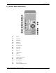
Contents 1 Product Description 1.1 System Design . . . . . . . . . . . . . . . . . . . . . . . . . . . . . . . . . . . . . . . . . . . . . . . . . . . . . . . . . . . . . . . 1.2 Computer Features. . . . . . . . . . . . . . . . . . . . . . . . . . . . . . . . . . . . . . . . . . . . . . . . . . . . . . . . . . . . 1.2.1 Front Panel Controls and LEDs . . . . . . . . . . . . . . . . . . . . . . . . . . . . . . . . . . . . . . . . . . . . . 1.2.2 Rear Panel Connectors . . . . . . . . . . . . . . . . . . . . .
Contents 4.2 Hood . . . . . . . . . . . . . . . . . . . . . . . . . . . . . . . . . . . . . . . . . . . . . . . . . . . . . . . . . . . . . . . . . . . . . . 4–2 4.3 Power Supply . . . . . . . . . . . . . . . . . . . . . . . . . . . . . . . . . . . . . . . . . . . . . . . . . . . . . . . . . . . . . . . 4–3 4.4 Mass Storage Devices . . . . . . . . . . . . . . . . . . . . . . . . . . . . . . . . . . . . . . . . . . . . . . . . . . . . . . . . . 4–4 4.4.1 CD (Optical) Drive . . . . . . . . . . . . . . . . .
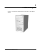
1 Product Description This chapter describes the model offerings and features of the Compaq Prosignia 340 Series Computer.
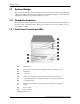
Product Description 1.1 System Design This section presents a functional descriptions of the key components of the Compaq Prosignia 340 Series Computer. All replaceable components are identified in Chapter 2, and removal and replacement instructions are presented in Chapters 3 and 4. 1.2 Computer Features The Compaq Prosignia 340 Series Computer ships with a mouse and keyboard.
Product Description 1.2.
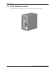
Product Description 1.3 Serial Number Location The serial number is located at the rear of the computer, below the power supply.
2 Spare Parts This chapter provides an illustrated parts breakdown and a listing of spare parts.
Spare Parts 2.
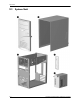
Spare Parts System Unit Item Description Spare Part 1 Front Bezel with bezel blank and power button 149804-001 2 Hood sssembly 149800-001 3 Chassis not spared 4 System rear I/O panel 149805-001 5 Power supply 136337-001 Compaq Prosignia Desktop 340 Series Computer 2–3
Spare Parts 2.
Spare Parts Mass Storage Devices Item 1 Description Diskette drive Spare Part 136338-001 Hard drive, 5400 RPM 2 4.3 GB 161431-001 * 8.
Spare Parts 2.
Spare Parts Cables Item Description Spare Part 1 Power switch with cable and LEDs 136340-001 * Power cord, U.S. 142766-001 Miscellaneous cable kit, includes 2 Hard drive cable, 10.5” (108950-007) * Diskette drive cable , 15.
Spare Parts 2.
Spare Parts Standard and Optional Boards Item Description Spare Part 1 System board 187672-001 Intel processor with heatsink and heatsink retaining clip 2 466 MHz Celeron 174742-001 533 MHz Celeron 176220-001 550 MHz Pentium III 176221-001 600 MHz Pentium III 176222-001 Memory module 3 32 MB 166890-001 * 64 MB 179190-001 * 128 MB 166966-001 4 56K, V.
Spare Parts 2.5 Miscellaneous Parts Miscellaneous Parts Item Description Spare Part 1 Diskette drive mounting bracket 161734-001 2 Hard drive mounting bracket 149807-001 3 Two-button mouse 166861-001 * Option slot cover (5 ea) 304284-001 * Creative Labs SBS52 speakers, Australia 125773-011 * Creative Labs SBS52 speakers, Europe 125773-021 * Creative Labs SBS52 speakers, Japan 125773-391 * Creative Labs SBS52 speakers, U.K. 125773-031 * Creative Labs SBS52 speakers, U.S.
Spare Parts 2.6 Keyboards Keyboards (not illustrated) Description Spare Part Internet keyboard Belgian 135510-181 French 135510-051 International 135510-B31 Spanish 135510-071 Swedish 135510-106 Swiss 135510-111 U.K. 135510-031 U.S. 135510-001 Spacesaver keyboard, Japanese 269513-291 2.
Spare Parts 2–12 Compaq Prosignia Desktop 340 Series Computer
3 Removal and Replacement Preliminaries and Routine Care This chapter provides general service information for the computer. Adherence to the procedures and precautions described in this chapter is essential for proper service. Ä 3.1 CAUTION: When the computer is plugged into an AC power source there is always voltage applied to the system board. You must disconnect the power cord from the power source before opening the computer to prevent system board or component damage.
Removal and Replacement Preliminaries and Routine Care 3.1.2 Preventing Electrostatic Damage to Equipment Many electronic components are sensitive to ESD. Circuitry design and structure determine the degree of sensitivity. The following proper packaging and grounding precautions are necessary to prevent damage to electric components and accessories. ■ To avoid hand contact, transport products in static-safe containers such as tubes, bags, or boxes.
Removal and Replacement Preliminaries and Routine Care 3.1.4 Grounding Workstations To prevent static damage at the workstation, use the following precautions: ■ Cover the workstation with approved static-dissipative material. Provide a wrist strap connected to the work surface and properly grounded tools and equipment. ■ Use static-dissipative mats, foot straps, or air ionizers to give added protection. ■ Handle electrostatic sensitive components, parts, and assemblies by the case or PCB laminate.
Removal and Replacement Preliminaries and Routine Care 3.2 Routine Care 3.2.1 3.2.1 General Cleaning Safety Precautions ■ Never use solvents or flammable solutions to clean the computer. ■ Never immerse any parts in water or cleaning solutions, apply any liquids to a clean cloth and then use the cloth on the component. ■ Always turn off the computer when cleaning with liquids or damp cloths. ■ Always turn off the computer before cleaning the keyboard, mouse, or air vents.
Removal and Replacement Preliminaries and Routine Care Ä ■ Visible debris underneath or between the keys may be removed by vacuuming or shaking. ■ Canned, pressurized air may be used to clean debris from under the keys. Caution should be used as too much air pressure can dislodge lubricants applied under the wide keys. ■ If you remove a key, use a specially designed key puller to prevent damage to the keys. This tool is available through many electronic supply outlets.
Removal and Replacement Preliminaries and Routine Care 3.3.2 Screws The screws used in the computer are not interchangeable. They may have standard or metric threads and may be of different lengths. If an incorrect screw is used during the reassembly process, it can damage the unit. Compaq strongly recommends that all screws removed during disassembly be kept with the part that was removed, then returned to their proper locations. 3.3.
4 Removal and Replacement Procedures After completing all necessary removal and replacement procedures, run the Diagnostics utility to verify that all components operate properly. Ä 4.1 CAUTION: When the computer is plugged into an AC power source, there is always voltage applied to the system board. You must disconnect the power cord from the power source before opening the computer to prevent system board or component damage.
Removal and Replacement Procedures 4.2 Hood 1. Prepare the computer for disassembly. 2. Unscrew the thumbscrews at the back of the computer. ✎ The screws will remain attached to the hood. 3. Grasp the bottom of the hood and pull back slightly while lifting the hood off the computer. To replace the hood, reverse this sequence.
Removal and Replacement Procedures 4.3 Power Supply 1. Remove the hood. 2. Disconnect all cables connected to the power supply (cables to the hard drive, CD drive, diskette drive, and system board). 3. Remove the four screws that secure the power supply to the rear of the chassis. 4. Slide the power supply to the front of the unit and remove it from the chassis. To replace the power supply, reverse this sequence.
Removal and Replacement Procedures 4.
Removal and Replacement Procedures 4.4.1 CD (Optical) Drive If a compact disc is jammed in the drive, insert a straightened paper clip into the manual eject hole and push firm1y. 1. Perform the preparation procedures. 2. Remove the hood. 3. Disconnect the audio 1, data 2, and power 3 cables from the CD drive.
Removal and Replacement Procedures 4. Remove the four screws from the side of the CD drive. 5. Pull the CD drive straight out of the front of the chassis. To replace the CD drive, reverse this sequence.
Removal and Replacement Procedures 4.4.2 Diskette Drive 1. Perform the preparation procedures. 2. Remove the hood. 3. Remove the power supply. (Section 4.3) Disconnect the power 1and data 2 cables from the diskette drive.
Removal and Replacement Procedures 4. Remove the screw that holds the diskette drive and bracket to the chassis. 5. Grasp the drive bracket assembly on both sides and pull it towards the rear of the chassis. 6. Remove the four screws from the sides of the bracket to release the drive from the bracket. To replace the diskette drive, reverse this sequence.
Removal and Replacement Procedures 4.4.3 Hard Drive 1. Perform the preparation procedures. 2. Remove the hood. 3. Disconnect the power 1 and signal 2 cables from the hard drive. 4. Remove the screw holding the hard drive and bracket to the chassis. 5. Carefully push the hard drive and bracket towards the other side of the computer, and lift them out of the chassis.
Removal and Replacement Procedures 6. Remove the four screws at the bottom of the hard drive bracket to release the hard drive. To replace the hard drive, reverse this sequence.
Removal and Replacement Procedures 4.5 Video Card 1. Perform the preparation procedures. 2. Remove the hood. 3. Remove the screw holding the video card bracket to the chassis, and pull the video card out of the slot. To replace the video card, reverse this sequence.
Removal and Replacement Procedures 4.6 Network Card 1. Perform the preparation procedures. 2. Remove the hood. 3. Remove the screw holding the network card bracket to the chassis, and pull the network card out of the slot. To replace the network card, reverse this sequence.
Removal and Replacement Procedures 4.7 Fax/Modem Card 1. Perform the preparation procedures. 2. Remove the hood. 3. Remove the screw holding the fax/modem bracket to the chassis, and pull the fax/modem card out of the slot. To replace the fax/modem card, reverse this sequence. Ä CAUTION: When replacing the fax/modem, download the latest SoftPaq containing the software from www.compaq.com. If QuickRestore is used, it may not have the 56K upgrade software included.
Removal and Replacement Procedures 4.8 Memory Module 1. Perform the preparation procedures. 2. Remove the hood. 3. Remove the power supply. 4. Release the latches 1 at each end of the DIMM socket and unplug the DIMM 2 from the system board. To replace the memory module, reverse this sequence.
Removal and Replacement Procedures 4.9 RTC Battery Å WARNING: This computer contains an internal lithium battery. There is a risk of fire and burns if the battery is not handled properly. To reduce the risk of personal injury: - Do not attempt to recharge the battery. - Do not expose to temperatures higher than 140 F (60 C). - Do not disassemble, crush, puncture, short circuit contacts, ordispose of in fire or water. - Replace battery only with the Compaq spare designated for this product. 1.
Removal and Replacement Procedures 4.10 Processor 1. Perform the preparation procedures. 2. Remove the hood. 3. Remove the power supply. (Section 4.3) 4. Locate the heatsink 2 on the system board. 5. Remove the clip 1 from the heatsink. 6. Carefully remove the heatsink from the processor 4 by twisting it before lifting it from the socket (the two are held together by an adhesive strip 8).
Removal and Replacement Procedures 4.11 Front Bezel 1. Perform the preparation procedures. 2. Remove the hood. 3. Release the latches at the middle and bottom of the bezel, then pivot the bezel up and away from the chassis. To replace the front bezel, reverse this sequence.
Removal and Replacement Procedures 4.12 On-Button Board 1. Perform the preparation procedures. 2. Remove the hood. 3. Remove the front bezel. (Section 4.11) 4. Disconnect the on-button board connector from the system board. 5. Remove the two screws from the button board assembly, and pull the board off the chassis. To replace the on-button board, reverse this sequence.
Removal and Replacement Procedures 4.13 System Board Bracket 1. Perform the preparation procedures. 2. Remove the hood. 3. Remove the modem. 4. Remove the network card. 5. Remove the video card. 6. Remove the screws holding the system board bracket to the chassis. 7. Slide the system board bracket toward the front bezel and carefully pull the bracket away from the chassis. 8. Disconnect the CD audio cable and data cable from the system board. 9.
Removal and Replacement Procedures 4.14 System Board 1. Perform the preparation procedures. 2. Remove the hood. 3. Remove the system board bracket. (Section 4.13) 4. Remove all of the cables from the system board. 5. Remove the eight screws that secure the system board to the bracket. To replace the system board, reverse this sequence.
Removal and Replacement Procedures 4.15 1/O Panel 1. Perform the preparation procedures. 2. Remove the hood. 3. Remove the system board bracket. 4. Gently push the I/O panel into the chassis from the rear of the unit. To replace the I/O panel, reverse this sequence.
Removal and Replacement Procedures 4–22 Compaq Prosignia Desktop 340 Series Computer
5 System Board Jumpers and Switches 5.
System Board Jumpers and Switches 5.2 Clearing and Setting Passwords Setting the Password provides access protection for the Computer Setup utility. Follow the instructions below to clear the password. 1. Turn off the computer and any external devices. 2. Disconnect the power cord from the power outlet. Å WARNING: The power cord must be disconnected from the power source before removing the access panel. Stray voltage on the system board may injure you. 3. Remove the access panel. 4.
System Board Jumpers and Switches 5.3 Resetting CMOS The computer's configuration (CMOS) may occasionally be corrupted. If it is, it is necessary to clear the CMOS memory using the CMOS button on the system board. To clear and reset the configuration, perform the following procedure: 1. Prepare the computer for disassembly. 2. Disconnect the power cord from the power outlet. 3. Remove the access panel. Å WARNING: The power cord must be disconnected from the power source before removing the access panel.
System Board Jumpers and Switches 5–4 Compaq Prosignia Desktop 340 Series Computer
Index A expansion card spare part number 2–8 access panel removal and replacement 4–2 audio cable spare part number 2–7 F B battery 3–6 removal and replacement 4–15 safety precautions 3–6 bezel blank spare parts number 2–3 C cables spare part number 2–7 CD-ROM cable spare part number 2–7 CD-ROM drive removal and replacement 4–5 CD-ROM drive spare part number 2–5 chassis spare part number 2–3 cleaning computer 3–4 keyboard 3–4 monitor 3–5 mouse 3–5 safety precautions 3–4 cleaning the keyboard 3–4 cleari
Index Network Interface Card (NIC) spare part number 2–9 O On-button board removal and replacement 4–18 optical drive cable spare part number 2–7 optical drive removal and replacement 4–5 option slot cover spare part number 2–10 P password setting and clearing 5–2 plastic parts safety precautions 3–6 power button/LED cable removal and replacement 4–18 power cord spare part number 2–7 power supply removal and replacement 4–3 power supply spare part number 2–3 power switch/LED cable spare part number 2–7 p
Index spare part number, chassis 2–3 speaker spare part number 2–10 standard and optional boards spare part number 2–8 static electricity 3–1 storage devices, location 4–4 switches, system board 5–1 system board bracket removal and assembly 4–19 jumpers and switches 5–1 removal and replacement 4–20 Compaq Prosignia Desktop 340 Series Computer spare part number 2–9 system unit spare part numbers 2–3 T tools required, service 3–5 V video card removal and replacement 4–11 Z Zip drive, spare part number 2
Index Compaq Prosignia Desktop 340 Series Computer Index–4