Reliable Transaction Router Getting Started Order Number: AA-RLE1A-TE January 2001 This document introduces Reliable Transaction Router and describes its concepts for the system manager, system administrator, and applications programmer. Revision/Update Information: This is a new manual. Software Version: Reliable Transaction Router Version 4.
© 2001 Compaq Computer Corporation Compaq, the Compaq logo, AlphaServer, TruCluster, VAX, and VMS Registered in U. S. Patent and Trademark Office. DECnet, OpenVMS, and PATHWORKS are trademarks of Compaq Information Technologies Group, L.P. Microsoft and Windows NT are trademarks of Microsoft Corporation. Intel is a trademark of Intel Corporation. UNIX and The Open Group are trademarks of The Open Group.
Contents Preface . . . . . . . . . . . . . . . . . . . . . . . . . . . . . . . . . . . . . . . . . . . . . . . . . . . . . vii 1 Introduction Reliable Transaction Router . . . . . . . . RTR Continuous Computing Concepts RTR Terminology . . . . . . . . . . . . . . . . RTR Server Types . . . . . . . . . . . . . . . RTR Networking Capabilities . . . . . . . . . . . . . . . . . . . . . . . . . . . . . . . . . . . . . . . . . . . . . . . . . . . . . . . . . . . . . . . . . . . . . . . . . . . .
3 Reliability Features Servers . . . . . . . . . . . . Failover and Recovery Router Failover . . Recovery Scenarios . . . Backend Recovery Router Recovery . Frontend Recovery . . . . . . . . . . . . . . . . . . . . . . . . . . . . . . . . . . . . . . . . . . . . . . . . . . . . . . . . . . . . . . . . . . . . . . . . . . . . . . . . . . . . . . . . . . . . . . . . . . . . . . . . . . . . . . . . . . . . . . . . . . . . . . . . . . . . . . . . . . . . . . . . . . . . . . . . . . . . .
Figures 1 1–1 1–2 1–3 1–4 1–5 1–6 1–7 1–8 1–9 1–10 1–11 1–12 1–13 1–14 1–15 1–16 1–17 1–18 1–19 1–20 2–1 2–2 4–1 5–1 5–2 RTR Reading Path . . . . . . . . . . . . . . . . . . . . . . . . . . . . . . . . . Client Symbol . . . . . . . . . . . . . . . . . . . . . . . . . . . . . . . . . . . . Server Symbol . . . . . . . . . . . . . . . . . . . . . . . . . . . . . . . . . . . . Roles Symbols . . . . . . . . . . . . . . . . . . . . . . . . . . . . . . . . . . . . Facility Symbol . . . . . . . . . . . . . . . . .
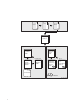
Preface Purpose of this Document The goal of this document is to assist an experienced system manager, system administrator, or application programmer to understand the Reliable Transaction Router (RTR) product. Document Structure This document contains the following chapters: • Chapter 1, Introduction to RTR, provides information on RTR technology, basic RTR concepts, and RTR terminology.
Related Documentation Additional resources in the RTR documentation kit include: Document Content For all users: Reliable Transaction Router Release Notes Describes new features, changes, and known restrictions for RTR. RTR Commands Lists all RTR commands, their qualifiers and defaults. For the system manager: Reliable Transaction Router Installation Guide Describes how to install RTR on all supported platforms.
Reader’s Comments Compaq welcomes your comments on this guide. Please send your comments and suggestions by email to rtrdoc@compaq.com. Please include the document title, date from title page, order number, section and page numbers in your message. For product information, send email to rtr@compaq.com. Conventions This manual adopts the following conventions: Convention Description New term New terms are shown in bold when introduced and defined.
Cover letter SPD Release Notes Figure 1 RTR Reading Path Getting Started Application Programmer System Manager Application Design Guide Installation Guide If V2 to V3 System Manager's Manual Migration Guide If C++ C Application Programmer's Reference Manual C++ Foundation Classes Commands = Tutorial ZKO-GS015-99AI x
1 Introduction This document introduces RTR and describes RTR concepts. It is intended for the system manager or administrator and for the application programmer who is developing an application that works with Reliable Transaction Router (RTR). Reliable Transaction Router Reliable Transaction Router (RTR) is failure-tolerant transactional messaging middleware used to implement large, distributed applications with client/server technologies.
RTR Continuous Computing Concepts RTR Continuous Computing Concepts RTR provides a continuous computing environment that is particularly valuable in financial transactions, for example in banking, stock trading, or passenger reservations systems.
RTR Terminology RTR Terminology The following terms are either unique to RTR or redefined when used in the RTR context. If you have learned any of these terms in other contexts, take the time to assimilate their meaning in the RTR environment.
RTR Terminology RTR Application An RTR application is user-written software that executes within the confines of several distributed processes. The RTR application may perform user interface, business, and server logic tasks and is written in response to some business need. An RTR application can be written in any language, commonly C or C++, and includes calls to RTR. RTR applications are composed of two kinds of actors, client applications and server applications.
RTR Terminology Figure 1–2 Server Symbol Channel RTR expects client and server applications to identify themselves before they request RTR services. During the identification process, RTR provides a tag or handle that is used for subsequent interactions. This tag or handle is called an RTR channel. A channel is used by client and server applications to exchange units of work with the help of RTR. An application process can have one or more client or server channels.
RTR Terminology Figure 1–3 Roles Symbols FE BE TR Facility The mapping between nodes and roles is done using a facility. An RTR facility is the user-defined name for a particular configuration whose definition provides the role-to-node map for a given application. Nodes can share several facilities. The role of a node is defined within the scope of a particular facility. The router is the only role that knows about all three roles.
RTR Terminology Figure 1–5 Components in the RTR Environment User Accounts Facility FE Client application TR BE Server application General Ledger Facility LKG-11203-98WI disconnected before all parts of the transaction are done, then the transaction remains incomplete. Transaction A transaction is a piece of work or group of operations that must be executed together to perform a consistent transformation of data.
RTR Terminology messaging, RTR ensures that a transaction is ‘‘all or nothing’’— either fully completed or discarded; either both the checking account debit and the savings account credit are done, or the checking account debit is backed out and not recorded in the database. RTR transactions have the ACID properties.
RTR Terminology Figure 1–6 Two-Tier Client/Server Environment DM Database Server Application Presentation and Business Logic (ODBC Model) LKG-11204-98WI Figure 1–7 Three-Tier Client/Server Environment DB Server Database Application Presentation/ User Interface Application Server/ Business Logic Database Server LKG-11205-98WI RTR provides a multicomponent software model where clients running on frontends, routers, and servers running on backends cooperate to provide reliable service and transactio
RTR Terminology All components can reside on a single node but are typically deployed on different nodes to achieve modularity, scalability, and redundancy for availability. With different systems, if one physical node goes down or off line, another router and backend node takes over. In a slightly different configuration, you could have an application that uses an external applet running on a browser that connects to a client running on the RTR frontend. Such a configuration is shown in Figure 1–8.
RTR Terminology single node configuration can be useful during development, but would not normally be used when your application is deployed. Figure 1–9 RTR with Browser, Single Node, and Database Browser FE TR BE DB LKG-11207-98WI When creating the configuration used by an application and defining the nodes where a facility has its frontends, routers, and backends, the setup must also define which nodes will have journal files.
RTR Terminology In this example, the frontend with the client and the router reside on one node, and the server resides on the backend. Frequently, routers are placed on backends rather than on frontends. A further separation of workload onto three nodes is shown in Figure 1–11.
RTR Terminology Figure 1–12 Standby Server Configuration BE Server Primary Server TR DB BE Server Standby Server LKG-11210-98WI Transactional shadowing To increase transaction availability, transactions can be shadowed with a shadow server. This is called transactional shadowing and is accomplished by having a second location, often at a different site, where transactions are also recorded. This is illustrated in Figure 1–13. Data are recorded in two separate data stores or databases.
RTR Terminology Figure 1–13 Transactional Shadowing Configuration BE Server FE Primary Server TR BE Server Shadow Server LKG-11211-98WI With transactional shadowing, there is no requirement that hardware, the data store, or the operating system at different sites be the same. You could, for example, have one site running OpenVMS and another running Windows NT; the RTR transactional commit process would be the same at each site.
RTR Server Types Figure 1–14 Two Sites: Transactional and Disk Shadowing with Standby Servers BE Disk Shadowing TR BE FE BE TR Transactional Shadowing BE LKG-11212-98WI Standby Server or Router RTR Server Types In the RTR environment, in addition to the placement of frontends, routers, and servers, the application designer must determine what server capabilities to use.
RTR Server Types • Concurrent servers • Callout servers These are described in the next few paragraphs. You specify server types to your application in RTR API calls. RTR server types help to provide continuous availability and a secure transactional environment. Standby server The standby server remains idle while the RTR primary backend server performs its work, accepting transactions and updating the database.
RTR Server Types one node can contain the primary servers for one key range and standby servers for another key range to balance the load across systems. This allows the nodes in a cluster environment to act as standby for other nodes without having idle hardware. When setting up a standby server, both servers must have access to the same journal.
RTR Server Types Figure 1–16 shows a simple shadow configuration. The main (BE) Server at Site 1 and the shadow server (Shadow) at Site 2 both receive every transaction for the data partition they are servicing. Should Site 1 fail, Site 2 continues to operate without interruption. Sites can be geographically remote, for example, available at separate locations in a wide area network (WAN).
RTR Server Types channels within a single process or as one channel in separate processes. Figure 1–17 Concurrent Servers BE Server1 Server2 Server3 A-N Server4 LKG-11275-98WI Callout server The callout server provides message authentication on transaction requests made in a given facility, and could be used, for example, to provide audit trail logging. A callout server can run on either backend or router nodes. A callout server receives a copy of all messages in a facility.
RTR Server Types Figure 1–18 A Callout Server Callout Server TR User Accounts Facility Application Server BE Transaction To Partition A LKG-11276-98WI Authentication RTR callout servers provide partition-independent processing for authentication. For example, a callout server can enable checks to be carried out on all requests in a given facility. Callout servers run on backend or router nodes. They receive a copy of every transaction either delivered to or passing through the node.
RTR Server Types When working with database systems, partitioning the database can be essential to ensuring smooth and untrammeled performance with a minimum of bottlenecks. When you partition your database, you locate different parts of your database on different disk drives to spread both the physical storage of your database onto different physical media and to balance access traffic across different disk controllers and drives.
RTR Server Types but strictly speaking, the key range defines the partition. A partition has both a name, its partition name, and an identifier generated by RTR — the partition ID. The properties of a partition (callout, standby, shadow, concurrent, key segment range) can be defined by the system manager with a CREATE PARTITION command. For details of the command syntax, see the RTR System Manager’s Manual.
RTR Networking Capabilities Figure 1–20 Standby with Partitioning 1-19999 Application ServerA 1-19999 Accounts: 1-19999 Router 1-19999 1-19999 20000-39999 Application ServerB 20000-39999 20000-39999 LKG-11214-98WI RTR Networking Capabilities Depending on operating system, RTR uses TCP/IP or DECnet as underlying transports for the virtual network (RTR facilities) and can be deployed in both local area and wide area networks. PATHWORKS 32 is required for DECnet configurations on Windows NT.
2 Architectural Concepts This chapter introduces concepts on basic transaction processing and RTR architecture. The Three-Layer Model RTR is based on a three-layer architecture consisting of frontend (FE) roles, backend (BE) roles and router (TR) roles. The roles are shown in Figure 2–1. In this and subsequent diagrams, rectangles represent physical nodes, ovals represent application software, and DB represents the disks storing the database (and usually the database software that runs on the server).
The Three-Layer Model Figure 2–1 The Three Layer Model Terminals Frontends (FE) Routers (TR) Backends (BE) Database (DB) BE FE Client Server DB BE FE Client Server DB TR DB BE FE Client Server TR FE Client ZKO-GS011-99AI • Allows performance or geographic expansion while protecting the investments made in existing hardware and application software. The router layer contains no application software unless running callout servers.
RTR Facilities Bridge the Gap RTR Facilities Bridge the Gap Many applications can use RTR at the same time without interfering with one another. This is achieved by defining a separate facility for each application. When an application calls the rtr_open_channel( ) routine to declare a channel as a client or server, it specifies the name of the facility it will use. See the RTR System Manager’s Manual for information on how to define facilities.
Flexibility and Growth • User access patterns • The volume of data Since an RTR-based system can be built using multiple systems at each functional layer, it easily lends itself to step-by-step growth, avoiding unused capacity at each stage. With your system still up and running, it is possible to: • Create and delete concurrent server processes. • Add or remove nodes (frontend, router or backend). This means you do not need to provide spare capacity to allow for growth.
The Partitioned Data Model The Partitioned Data Model One goal in designing for high transaction throughput is reducing the time that users must wait for shared resources. While many elements of a transaction processing system can be duplicated, one resource that must be shared is the database.
Object-Oriented Programming Figure 2–2 Partitioned Data Model Terminals Frontends (FE) Routers (TR) Backends (BE) Database (DB) BE FE Client Server BE FE Client Server TR BE FE Client DB DB DB Server TR FE Client ZKO-GS012-99AI 2–6 Architectural Concepts
Object-Oriented Programming Table 2–1 Functional and Object-Oriented Programming Compared Objects Functional Programming Object-Oriented Programming A program consists of data structures and algorithms. A program consists of a team of cooperating objects. The basic programming unit is the function, that when run, implements an algorithm. The basic programming unit is the class, that when instantiated, implements an object. Functions operate on elemental data types or data structures.
Object-Oriented Programming Example 2–1 Objects-Defined Sample Dog.h: class Dog { ... }; main.cpp: #include "Dog.h" main() { Dog King; Dog Fifi; } Messages Objects communicate by sending messages. This is done by calling an object’s methods. Some principal categories of messages are: Class Relationships • Constructors: Create objects • Destructors: Delete objects • Selectors: Return part or all of an object’s state. For example, a Get method • Modifiers: Change part or all of an object’s state.
Object-Oriented Programming Polymorphism Polymorphism is the ability of objects, inherited from a common base or parent class, to respond differently to the same message. This is done by defining different implementations of the same method name within the individual child class definitions. For example: A DogArray object, "DogArray OurDogs[2];" refers to two element objects of class Dog, the base class: • King, of class Doberman, is a derived or child class of Dog.
XA Support XA Support The XA interface is part of the X/Open DTP (Distributed Transaction Processing) standard. It defines the interface that transaction managers (TM) and resource managers (RM) use to perform the two-phase commit protocol. (Resource managers are underlying database systems such as ORACLE RDBMS, Microsoft SQL Server, and others.) This interface is not used by the application programs; it is only used by TM-to-RM exchanges to coordinate a transaction.
3 Reliability Features Reliability in RTR is enhanced by the use of: • Concurrent servers • Standby servers • Shadow servers • Callout servers • Router failover Servers Note that, conceptually, servers can be contrasted as follows: • Concurrent servers handle similar transactions which access the same data partition and run on the same node. • Shadow servers handle the same transactions and run on different nodes.
Failover and Recovery Failover and Recovery RTR provides several capabilities to ensure failover and recovery under several circumstances. Router Failover Frontend nodes automatically connect to another router if the one being used fails. This reconnection is transparent to the application. Routers are responsible for coordinating the two-phase commit for transactions.
Recovery Scenarios Backend Recovery If standby or shadow servers are available on another backend node, operation of the rest of the system will continue without interruption, using the standby or shadow server. If a backend processor is lost, any transactions in progress are remembered by RTR and later recovered, either when the backend restarts, or by a standby if one is present. Thus, the distributed database is brought back to a transaction-consistent state.
4 RTR Interfaces RTR provides interfaces for management and application programming. You manage RTR with a management interface from the RTR management station. The management interfaces are: • The command line interface or CLI • The browser interface The application programming interfaces (APIs) are: • The object-oriented API for C++ programming, available with RTR Version 4.0. Use this API for all new development and, where appropriate, for new work on existing applications.
The RTR application programming interfaces are identical on all hardware and operating system platforms that support RTR. The object-oriented API is fully described in the manual Reliable Transaction Router C++ Foundation Classes. The Cprogramming API is fully described in the Reliable Transaction Router C Application Programmer’s Reference Manual. Both APIs are used in designs in the RTR Application Design Guide.
RTR Management Station The user is called user, the facility being defined is called DESIGN, a client and a server are established, and a test message containing the words "Kathy’s text today" is sent from the client to the server. After the server receives this text, the user on the server enters the words "And this is my response." System responses begin with the characters % RTR-. Notes on the procedure are enclosed in square brackets [ ]. For clarity, commands you enter are shown in bold.
RTR Management Station [The user issues the following commands on the server application where RTR is running on the backend.] $ RTR Copyright Compaq Computer Corporation 1994.
RTR Management Station RTR> RTR_RECEIVE_MESSAGE/CHAN=S %RTR-S-OK, normal successful completion channel name: S msgsb msgtype: rtr_mt_msg1 msglen: 19 usrhdl: 0 Tid: 63b01d10,0,0,0,0,2e59,43ea2002 message offset bytes text 000000 4B 61 74 68 79 27 73 20 74 65 78 74 20 74 6F 64 Kathy’s text tod 000010 61 79 00 ay. reason: Ox00000000 RTR> RTR_REPLY_TO_CLIENT/CHAN=S "And this is my response.
RTR Management Station RTR> RTR_RECEIVE_MESSAGE/CHANNEL=C/tim [to get mt_opened or mt_closed] %RTR-S-OK, normal successful completion channel name: C msgsb msgtype: rtr_mt_opened msglen: 8 message status: normal successful completion reason: Ox00000000 RTR> RTR_START_TX/CHAN=C %RTR-S-OK, normal successful completion RTR> RTR_SEND_TO_SERVER/CHAN=C "Kathy’s text today.
RTR Management Station RTR> RTR_RECEIVE_MESSAGE %RTR-S-OK, normal successful completion channel name: S . . . msgtype: rtr_mt_accepted . . . RTR> STOP RTR Browser Interface With the RTR browser interface, your management station has a network-browser-like display from which you can view RTR status and issue RTR certain commands with a point-and-click operation, rather than by entering commands.
Application Programming Interfaces Figure 4–1 RTR Browser Interface Sample C++ client code Example of object creation in an RTR client program. // // Create a Transaction Controller to receive incoming messages // and events from a client. // RTRClientTransactionController *pTransaction = new RTRClientTransactionController(); // // Create an RTRData object to hold an ASCII message for the server.
Application Programming Interfaces Sample C++ server code Example of object creation in an RTR server program. void CombinationOrderProcessor::StartProcessingOrdersAtoL() { // // Create an RTRKeySegment for all ASCII values between "A" and "L." // m_pkeyRange = new RTRKeySegment (rtr_keyseg_string, //To process strings. 1, //Length of the key. OffsetIntoApplicationProtocol, //Offset value. "A", //Lowest ASCII value for partition. "L"); //Highest ASCII value for partition.
Application Programming Interfaces Sample C client code Example of an open channel call in an RTR client program: Sample C server code Example of a receive message call in an RTR server program: status = rtr_open_channel(&Channel, Flags, Facility, Recipient, RTR_NO_PEVTNUM, Access, RTR_NO_NUMSEG, RTR_NO_PKEYSEG); if (Status != RTR_STS_OK) status = rtr_receive_message(&Channel, RTR_NO_FLAGS, RTR_ANYCHAN, MsgBuffer, DataLen, RTR_NO_TIMOUTMS, &MsgStatusBlock); if (status != RTR_STS_OK) A client can have
5 The RTR Environment The RTR environment has two parts: • The system management environment • The runtime environment The RTR System Management Environment You manage your RTR environment from a management station, which can be on a node running RTR or on some other node. You can manage your RTR environment either from your management station running a network browser, or from the command line using the RTR CLI.
The RTR System Management Environment • Handles all transactions and recovery RTRACP handles interprocess communication traffic, network traffic, and is the main repository of runtime information. ACP processes operate across all RTR roles and execute certain commands both locally and at remote nodes.
The RTR System Management Environment The Command Server Process executes commands both locally and across nodes. Commands that can be executed at the RTR COMSERV include: • START RTR • CREATE/MODIFY JOURNAL • SHOW LINK/FACILITY/SERVER/CLIENT (ACP must be running) • Application programmer commands (for testing and demonstration) The RTR system management environment is illustrated in Figure 5–1.
The RTR System Management Environment Monitoring RTR RTR Monitor pictures or the RTR Monitor let you view the status and activities of RTR and your applications. A monitor picture is dynamic, its data periodically updated. RTR SHOW commands that also let you view status are snapshots, giving you a view at one moment in time. A full list of RTR Monitor pictures is available in the RTR System Manager’s Manual ‘‘RTR Monitoring’’ chapter and in the help file under RTR_Monitoring.
The RTR System Management Environment Partition Management Partitions are subdivisions of a routing key range of values used with a partitioned data model and RTR data-content routing. Partitions exist for each range of values in the routing key for which a server is available to process transactions. Redundant instances of partitions can be started in a distributed network, to which RTR automatically manages the state and flow of transactions.
The RTR Runtime Environment • Server application • RTR shareable image, LIBRTR • RTR control process, RTRACP • RTR daemon, RTRD Figure 5–2 shows these components and their placement on frontend, router, and backend nodes. The frontend, router, and backend can be on the same or different nodes. If these are all on the same node, there is only one RTRACP process.
What’s Next? What’s Next? This concludes the material on RTR concepts and capabilities that all users and implementors should know. For more information, proceed as follows: If you are: Read these documents: a system manager, system administrator, or software installer 1. RTR Release Notes 2. RTR Installation Guide 3. RTR Migration Guide (if upgrading from RTR V2 to V3) 4.
Glossary A few additional terms are defined in the Glossary to the Reliable Transaction Router Application Design Guide. ACID Transaction properties supported by RTR: atomicity, consistency, isolation, durability. ACP The RTR Application Control Process. API Application Programming Interface. applet A small application designed for running on a browser. application User-written software that uses employs RTR. application classes The C++ API classes used for implementing client and server applications.
branch A subdivision of a bank; perhaps in another town. broadcast A nontransactional message. callout server A server process used for transactional authentication. channel A logical port opened by an application with an identifier to exchange messages with RTR. client A client is always a client application, one that initiates and demarcates a piece of work. In the context of RTR, a client must run on a node defined to have the frontend role.
common classes C++ foundation classes that can be used in both client and server applications. concurrent server A server process identical to other server processes running on the same node. CPU Central processing unit. data marshalling The capability of using systems of different architectures (big endian, little endian) within one application. data object See RTRData object.
endian The byte-ordering of multibyte values. Big endian: high-order byte at starting address; little endian: low-order byte at starting address. event RTR or application-generated information about an application or RTR. event driven A processing model in which the application receives messages and events by registering handlers with the transaction controller. These handlers are derived from the C++ foundation class message and event-handler classes.
frontend FE, the physical node in an RTR facility where the client application runs. FTP File transfer protocol. inquorate Nodes/roles that cannot participate in a facility’s transactions are inquorate. journal A file containing transactional messages used for recovery. key range An attribute of a key segment, for example a range A to E or F to K. key segment An attribute of a partition that defines the type and range of values that the partition handles. LAN Local area network.
message A logical grouping of information transmitted between software components, typically over network links. message handler A C++ API-derived object used in event-driven processing that processes messages. multichannel An application that uses more than one channel. A server is usually multichannel. multithreaded An application that uses more than one thread of execution in a single process. MS DTC Microsoft DTC; see DTC. node A physical system.
primary The state of the partition servicing the original data store or database. A primary has a secondary or shadow counterpart. process The basic software entity, including address space, scheduled by system software, that provides the context in which an image executes. properties Application, transaction and system information. property classes Classes used for obtaining information about facilities, partitions, and transactions. quorate Nodes/roles in a facility that has quorum are quorate.
rollback When a transaction has been committed on the primary database but cannot be committed on its shadow, the committed transaction must be removed or rolled back to restore the database to its pre-transaction state. router The RTR role that manages traffic between RTR clients and servers. RTR configuration The set of nodes, disk drives, and connections between them used by RTR. RTR environment The RTR run-time and system management areas. RTRData object An instance of the C++ API RTRData class.
shadow The state of the server process that services a copy of the data store or primary database. In the context of RTR, the shadow method is transactional shadowing, not disk shadowing. Its counterpart is primary. SMP Symmetric MultiProcessing. standby The state of the partition that can take over if the process for which it is on standby is unavailable. It is held in reserve, ready for use. TPS Transactions per second.
transactional message A message containing transactional data. transactional shadowing A process by which identical transactional data are written to separate disks often at separate sites to increase data availability in the event of site failure. See also disk shadowing. two-phase commit A database commit/rollback concept that works in two steps: 1. The coordinator asks each local recovery manager if it is able to commit the transaction. 2.
Index A ACID, 2–4 Anonymous client, 1–22 API, 4–1 Application distributed, 2–4 software, 2–2 Authentication, 1–20 B Backend, 2–1 loss, 3–3 BE, 2–1 Broadcast, 2–3 DECnet, 1–23 Distributed applications, 2–4 DTP standard, 2–10 F Facility, 2–3 Failure tolerance, 3–2 Fault tolerance, 3–2 FE, 2–1 Firewall tunneling software, 1–22 Frontend, 2–1 CPU loss, 3–3 K Key range, 1–16 C L Callout server, 1–20, 3–1 Client anonymous, 1–22 processes, 2–1 Concurrent server, 3–1 LAN, 1–23 Link failure recovery, 3–2 Load
N Network wide area, 1–18 Nodes, 2–2 O Object-oriented, 2–5 Oracle RDBMS, 2–10 P Parallel execution, 2–4 Partitioned data model, 2–5 Processes client, 2–1 server, 2–1 R RDBMS, 2–10 Recovery, 3–2 Reliability features, 3–1 Resource manager, 2–10 RM, 2–10 Router, 2–1 failover, 3–2 layer, 2–2 loss, 3–3 RTR API, 4–1 broadcasts, 2–3 facilities, 2–3 flexibility and growth, 2–3 reliability features, 3–1 S Security check, 1–20 Server callout, 3–1 concurrent, 3–1 Index–2 Server (cont’d) shadow, 3–1 spare, 1–16