
Specifications

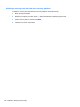


Table Of Contents
- Product description
- External component identification
- Illustrated parts catalog
- Removal and replacement procedures
- Computer Setup
- Specifications
- Screw listing
- Phillips PM2.0×5.0 captive screw
- Phillips PM2.5×13.0 captive screw
- Phillips PM3.0×4.0 screw
- Phillips PM2.5×4.0 screw
- Torx T8M2.5×7.0 screw
- Phillips PM2.0×4.0 screw
- Torx T8M2.5×9.0 screw
- Torx T8M2.5×3.0 broad-head screw
- Torx T8M2.5×4.0 screw
- Torx T8M2.5×6.0 screw
- Phillips PM2.0×2.0 broad-head screw
- Phillips PM2.0×6.0 screw
- Phillips PM2.5×7.0 screw
- Phillips PM2.5×7.0 captive screw
- Phillips PM2.5×10.0 captive screw
- Backup and recovery
- Connector pin assignments
- Power cord set requirements
- Recycling
- Index
Perform the following steps to disassemble the display assembly:
1. Remove all screw covers (1) and screws (2) that secure the display bezel to the display assembly.
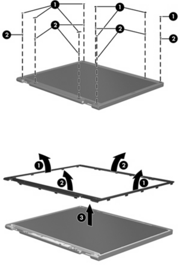
2. Lift up and out on the left and right inside edges (1) and the top and bottom inside edges (2) of the
display bezel until the bezel disengages from the display assembly.
3. Remove the display bezel (3).
130 Chapter 11 Recycling