
Specifications


Table Of Contents
- Product description
- External component identification
- Illustrated parts catalog
- Removal and replacement procedures
- Computer Setup
- Specifications
- Screw listing
- Phillips PM2.0×5.0 captive screw
- Phillips PM2.5×13.0 captive screw
- Phillips PM3.0×4.0 screw
- Phillips PM2.5×4.0 screw
- Torx T8M2.5×7.0 screw
- Phillips PM2.0×4.0 screw
- Torx T8M2.5×9.0 screw
- Torx T8M2.5×3.0 broad-head screw
- Torx T8M2.5×4.0 screw
- Torx T8M2.5×6.0 screw
- Phillips PM2.0×2.0 broad-head screw
- Phillips PM2.0×6.0 screw
- Phillips PM2.5×7.0 screw
- Phillips PM2.5×7.0 captive screw
- Phillips PM2.5×10.0 captive screw
- Backup and recovery
- Connector pin assignments
- Power cord set requirements
- Recycling
- Index
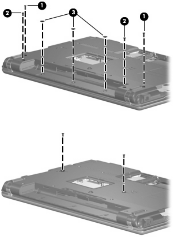
Remove the switch cover and keyboard:
1. Remove the following screws:
(1) Two Torx T8M2.5×9.0 screws
(2) Two Torx T8M2.5×7.0 screws
(3) Three Torx T8M2.5×3.0 broad-head screws
2. Remove the two Torx T8M2.5×7.0 screws that secure the keyboard to the computer.
3. Turn the computer display-side up, with the front toward you.
4. Open the computer as far as possible.
46 Chapter 4 Removal and replacement procedures