
Specifications


Table Of Contents
- Product description
- External component identification
- Illustrated parts catalog
- Removal and replacement procedures
- Computer Setup
- Specifications
- Screw listing
- Phillips PM2.0×5.0 captive screw
- Phillips PM2.5×13.0 captive screw
- Phillips PM3.0×4.0 screw
- Phillips PM2.5×4.0 screw
- Torx T8M2.5×7.0 screw
- Phillips PM2.0×4.0 screw
- Torx T8M2.5×9.0 screw
- Torx T8M2.5×3.0 broad-head screw
- Torx T8M2.5×4.0 screw
- Torx T8M2.5×6.0 screw
- Phillips PM2.0×2.0 broad-head screw
- Phillips PM2.0×6.0 screw
- Phillips PM2.5×7.0 screw
- Phillips PM2.5×7.0 captive screw
- Phillips PM2.5×10.0 captive screw
- Backup and recovery
- Connector pin assignments
- Power cord set requirements
- Recycling
- Index
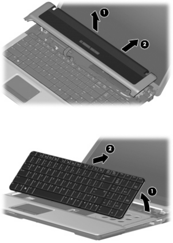
5. Lift the switch cover (1) straight up until it disengages from the computer, and slide it back (2) until
it rests on the display assembly.
6. Lift the rear edge of the keyboard (1) until it rests at an angle, and slide it back (2) until it rests on
the display assembly and switch cover.
Component replacement procedures 47