
Specifications


Table Of Contents
- Product description
- External component identification
- Illustrated parts catalog
- Removal and replacement procedures
- Computer Setup
- Specifications
- Screw listing
- Phillips PM2.0×5.0 captive screw
- Phillips PM2.5×13.0 captive screw
- Phillips PM3.0×4.0 screw
- Phillips PM2.5×4.0 screw
- Torx T8M2.5×7.0 screw
- Phillips PM2.0×4.0 screw
- Torx T8M2.5×9.0 screw
- Torx T8M2.5×3.0 broad-head screw
- Torx T8M2.5×4.0 screw
- Torx T8M2.5×6.0 screw
- Phillips PM2.0×2.0 broad-head screw
- Phillips PM2.0×6.0 screw
- Phillips PM2.5×7.0 screw
- Phillips PM2.5×7.0 captive screw
- Phillips PM2.5×10.0 captive screw
- Backup and recovery
- Connector pin assignments
- Power cord set requirements
- Recycling
- Index
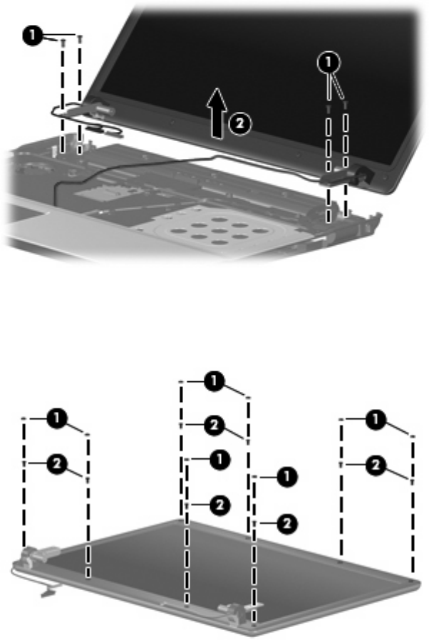
4. Lift the display assembly (2) straight up and remove it.
5. If it is necessary to replace the display bezel, display inverter, or display hinges, remove the eight
rubber screw covers (1) and the eight Torx T8M2.5×6.0 screws (2) that secure the display bezel
to the display assembly. The rubber screw covers are available in the Rubber Kit, spare part number
456616-001.
6. Flex the inside edges of the left and right sides (1) and the top and bottom sides (2) of the display
bezel until the bezel disengages from the display enclosure.
52 Chapter 4 Removal and replacement procedures