
Specifications


Table Of Contents
- Product description
- External component identification
- Illustrated parts catalog
- Removal and replacement procedures
- Computer Setup
- Specifications
- Screw listing
- Phillips PM2.0×5.0 captive screw
- Phillips PM2.5×13.0 captive screw
- Phillips PM3.0×4.0 screw
- Phillips PM2.5×4.0 screw
- Torx T8M2.5×7.0 screw
- Phillips PM2.0×4.0 screw
- Torx T8M2.5×9.0 screw
- Torx T8M2.5×3.0 broad-head screw
- Torx T8M2.5×4.0 screw
- Torx T8M2.5×6.0 screw
- Phillips PM2.0×2.0 broad-head screw
- Phillips PM2.0×6.0 screw
- Phillips PM2.5×7.0 screw
- Phillips PM2.5×7.0 captive screw
- Phillips PM2.5×10.0 captive screw
- Backup and recovery
- Connector pin assignments
- Power cord set requirements
- Recycling
- Index
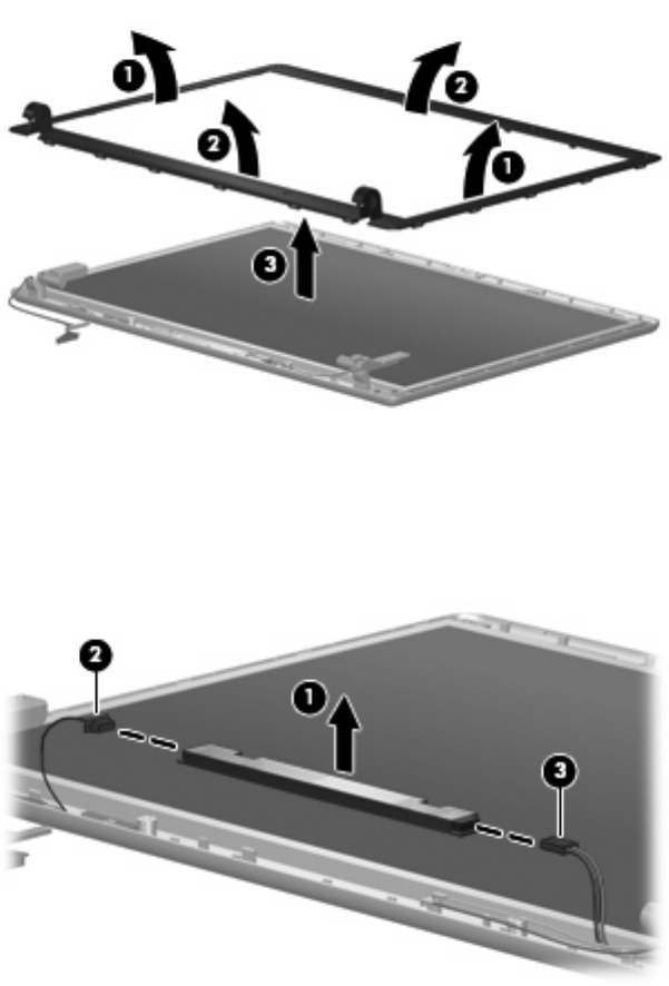
7. Remove the display bezel (3). The display bezel is available in the display enclosure kit using spare
part number 456586-001.
8. If it is necessary to replace the display inverter, remove the inverter (1) from the display enclosure
as far as the display panel cable and the backlight cable will allow.
9. Disconnect the display panel cable (2) and the backlight cable (3) from the display inverter.
10. Remove the display inverter. The display inverter is available using spare part number
457621-001.
11. If it is necessary to replace the display hinges, remove the four Torx T8M2.5×6.0 screws (1) that
secure the display panel to the display enclosure.
Component replacement procedures 53