
Specifications


Table Of Contents
- Product description
- External component identification
- Illustrated parts catalog
- Removal and replacement procedures
- Computer Setup
- Specifications
- Screw listing
- Phillips PM2.0×5.0 captive screw
- Phillips PM2.5×13.0 captive screw
- Phillips PM3.0×4.0 screw
- Phillips PM2.5×4.0 screw
- Torx T8M2.5×7.0 screw
- Phillips PM2.0×4.0 screw
- Torx T8M2.5×9.0 screw
- Torx T8M2.5×3.0 broad-head screw
- Torx T8M2.5×4.0 screw
- Torx T8M2.5×6.0 screw
- Phillips PM2.0×2.0 broad-head screw
- Phillips PM2.0×6.0 screw
- Phillips PM2.5×7.0 screw
- Phillips PM2.5×7.0 captive screw
- Phillips PM2.5×10.0 captive screw
- Backup and recovery
- Connector pin assignments
- Power cord set requirements
- Recycling
- Index
3. Turn the computer right-side up, with the left side toward you.
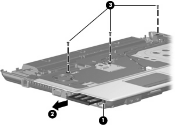
4. Press in on the ExpressCard slot eject button (1) two times. The first press releases the
ExpressCard slot eject button. The second press releases the ExpressCard slot bezel from the
ExpressCard slot.
5. Remove the ExpressCard slot bezel (2).
6. Remove the three Torx T8M2.5×7.0 screws (3) that secure the top cover to the computer.
7. Lift the rear edge of the top cover (1) and swing it up and forward until it rests at an angle.
8. Lift the front edge of the top cover (2) until it disengages from the base enclosure.
9. Tilt the top cover (3) back until the TouchPad cable is accessible.
56 Chapter 4 Removal and replacement procedures