
Specifications


Table Of Contents
- Product description
- External component identification
- Illustrated parts catalog
- Removal and replacement procedures
- Computer Setup
- Specifications
- Screw listing
- Phillips PM2.0×5.0 captive screw
- Phillips PM2.5×13.0 captive screw
- Phillips PM3.0×4.0 screw
- Phillips PM2.5×4.0 screw
- Torx T8M2.5×7.0 screw
- Phillips PM2.0×4.0 screw
- Torx T8M2.5×9.0 screw
- Torx T8M2.5×3.0 broad-head screw
- Torx T8M2.5×4.0 screw
- Torx T8M2.5×6.0 screw
- Phillips PM2.0×2.0 broad-head screw
- Phillips PM2.0×6.0 screw
- Phillips PM2.5×7.0 screw
- Phillips PM2.5×7.0 captive screw
- Phillips PM2.5×10.0 captive screw
- Backup and recovery
- Connector pin assignments
- Power cord set requirements
- Recycling
- Index
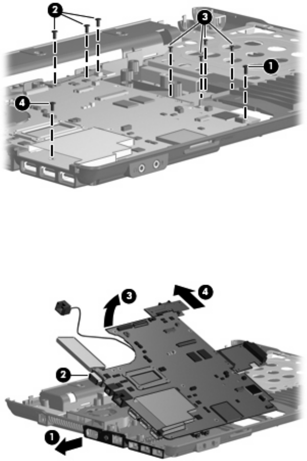
3. Remove the following screws:
(1) One Torx T8M2.5×6.0 screw that secures the system board to the base enclosure
(2) Three Torx T8M2.5×6.0 screws that secure the battery connector board to the base enclosure
(3) Four Torx T8M2.5×4.0 screws that secure the optical drive connector board to the base
enclosure
(4) One Phillips PMM2.0×6.0 screw that secures the system board to the base enclosure
4. Flex the left side of the base enclosure (1) until the external monitor connector (2) is clear of the
opening in the base enclosure.
5. Lift the rear edge of the system board (3) until it rests at an angle.
6. Remove the system board (4) from the base enclosure by sliding it back.
Component replacement procedures 63