
Specifications


Table Of Contents
- Product description
- External component identification
- Illustrated parts catalog
- Removal and replacement procedures
- Computer Setup
- Specifications
- Screw listing
- Phillips PM2.0×5.0 captive screw
- Phillips PM2.5×13.0 captive screw
- Phillips PM3.0×4.0 screw
- Phillips PM2.5×4.0 screw
- Torx T8M2.5×7.0 screw
- Phillips PM2.0×4.0 screw
- Torx T8M2.5×9.0 screw
- Torx T8M2.5×3.0 broad-head screw
- Torx T8M2.5×4.0 screw
- Torx T8M2.5×6.0 screw
- Phillips PM2.0×2.0 broad-head screw
- Phillips PM2.0×6.0 screw
- Phillips PM2.5×7.0 screw
- Phillips PM2.5×7.0 captive screw
- Phillips PM2.5×10.0 captive screw
- Backup and recovery
- Connector pin assignments
- Power cord set requirements
- Recycling
- Index
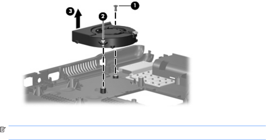
3. Remove the fan (3) from the base enclosure.
Reverse this procedure to install the fan.
NOTE: To properly ventilate the computer, allow at least a 7.6-cm (3-inch) clearance on the left side
of the computer.
The computer uses an electric fan for ventilation. The fan is controlled by a temperature sensor and is
designed to turn on automatically when high temperature conditions exist. These conditions are affected
by high external temperatures, system power consumption, power management/battery conservation
configurations, battery fast charging, and software requirements. Exhaust air is displaced through the
ventilation grill located on the left side of the computer.
66 Chapter 4 Removal and replacement procedures