
Specifications


Table Of Contents
- Product description
- External component identification
- Illustrated parts catalog
- Removal and replacement procedures
- Computer Setup
- Specifications
- Screw listing
- Phillips PM2.0×5.0 captive screw
- Phillips PM2.5×13.0 captive screw
- Phillips PM3.0×4.0 screw
- Phillips PM2.5×4.0 screw
- Torx T8M2.5×7.0 screw
- Phillips PM2.0×4.0 screw
- Torx T8M2.5×9.0 screw
- Torx T8M2.5×3.0 broad-head screw
- Torx T8M2.5×4.0 screw
- Torx T8M2.5×6.0 screw
- Phillips PM2.0×2.0 broad-head screw
- Phillips PM2.0×6.0 screw
- Phillips PM2.5×7.0 screw
- Phillips PM2.5×7.0 captive screw
- Phillips PM2.5×10.0 captive screw
- Backup and recovery
- Connector pin assignments
- Power cord set requirements
- Recycling
- Index
d. Speaker (see Speaker on page 49)
e. Display lid switch module (see
Display lid switch module on page 50)
f. Display assembly (see
Display assembly on page 51)
g. Top cover (see
Top cover on page 55)
h. System board (see
System board on page 61)
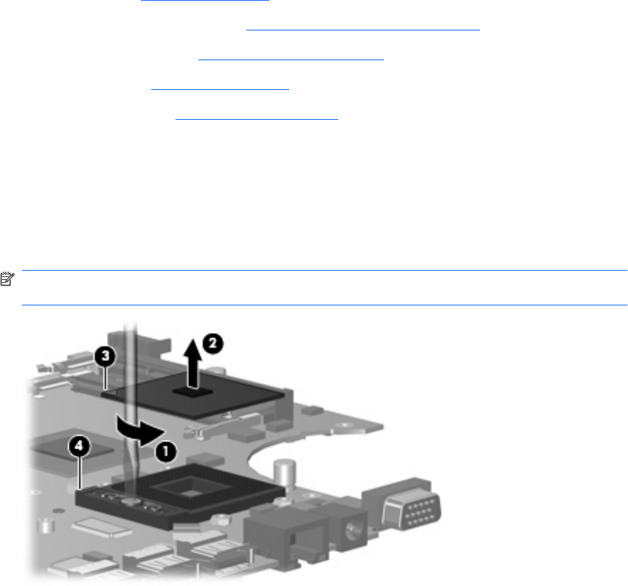
Remove the processor:
1. Turn the system board upside down, with the USB connectors toward you.
2. Use a flat-bladed screwdriver to turn the processor locking screw (1) one-half turn counterclockwise
until you hear a click.
3. Lift the processor (2) straight up and remove it.
NOTE: When you install the processor, the gold triangle (3) on the processor must be aligned
with the triangle (4) embossed on the processor slot.
Reverse this procedure to install the processor.
70 Chapter 4 Removal and replacement procedures