
User guide
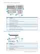

2 Hardware Installation
This section details the steps to install the VLS hardware from installation preparation to final cabling.
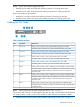
Minimum Hardware Requirements
VLS12000 systems upgrading to firmware 6.1 have the following hardware requirements:
• Minimum system disk size is 120 GB, so systems with 60 GB drives must upgrade the drives
• Minimum memory is 16 GB of RAM, so systems with 4 GB of RAM must upgrade the memory
Preparing for the Installation
Prepare the EVA for the VLS12000 Gateway
Arrays that will be connected to the VLS Gateway must already be setup with the appropriate
configuration as described in the solutions guide, including:
• Command View EVA is installed, at firmware revision 5100 or later, and functioning properly.
• There are either two external Fibre Channel switches/fabrics or two zones on an external
Fibre Channel switch/fabric so that there are two (high availability) data pathways from the
VLS Gateway to the EVA.
• All of the VRaid LUNs required for the VLS have been created on the EVA according to the
design guidelines (for example, each LUN is roughly the same size—2 TB is preferred. The
LUNs can not be read-only. RAID 5 is recommended. Path failover is balanced across both
EVA controllers).
NOTE: Minimum capacity for EVA LUNs is 100 GB. Ensure all EVA LUNs attached to the
Gateway meet this requirement.
If this has not been done, refer to the solutions guide for instructions.
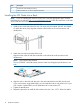
Tools for Installation
• Two people
• #1 and #2 Phillips screwdriver
• Box cutting knife
CAUTION: Do not use any power tools. They could strip or damage connections.
Taking ESD Precautions
To prevent damaging the system, be aware of the precautions you need to follow when setting up
the system or handling parts. A discharge of static electricity from a finger or other conductor may
damage system boards or other static-sensitive devices. This type of damage may reduce the life
expectancy of the device.
To prevent electrostatic damage:
• Avoid hand contact by transporting and storing products in static-safe containers.
• Keep electrostatic-sensitive parts in their containers until they arrive at static-free workstations.
• Place parts on a grounded surface before removing them from their containers.
• Avoid touching pins, leads, or circuitry.
• Always be properly grounded when touching a static-sensitive component or assembly.
12 Hardware Installation