
User guide
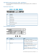
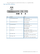
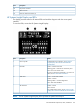
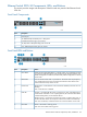
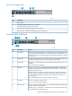

Front Panel Components
DescriptionItem
Console port1
10/100/1000Base-T RJ-45 ports 1 through 20
(numbered from top to bottom, left to right)
2
10/100/1000–T dual-personality ports 21 through 243
10/100/1000 mini-GBIC dual-personality ports 21 through 244
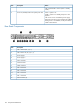
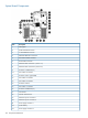
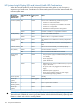
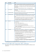
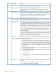
Front Panel LEDs and Buttons
StatusDescriptionItem
When pressed with the Reset button in a specific pattern, any configuration changes
you may have made through the switch console, the Web browser interface, and
Clear button1
SNMP management are removed, and the factory default configuration is restored
to the switch.
Used to reset the switch while it is turned on. This action clears any temporary error
conditions that may have occurred and executes the switch self-test.
Reset button2
Blinking blue = Locate function is active. Firmware controlled, can be set to on or
blinking.
Locator LED3
Off = Locate function is disabled.
Orange = The switch has encountered a fatal hardware failure or has failed its
self-test. This LED comes on briefly after the switch is powered on or reset, at the
beginning of switch self test.
Fault LED4
Blinking orange
1
= A fault has occurred on the switch, one of the switch ports, or
the fan. The status LED for the component with the fault will blink simultaneously.
If just the Fault LED is blinking, the switch could be attached to an RPS but not
receiving power.
Off = Indicates that there are no fault conditions on the switch.
Green = The switch is receiving power.Power LED5
Off = The switch is not receiving power.
Green = An HP ProCurve EPS/RPS unit is connected and operating correctly. The
EPS/RPS could be powering the unit.
RPS status LED6
Blinking green
1
= The EPS/RPS is connected but may be powering another switch
or the EPS/RPS has experienced a fault.
Ethernet Switch 2810–24G Components, LEDs, and Buttons 159