
User guide

DescriptionItem
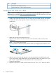
Printed VLS node installation poster (1)6
Ethernet cables (2), not shown (shipped separately)
Installing the VLS Node into a Rack
NOTE: If you are installing the node into a telco rack, order the appropriate option kit at the
RackSolutions.com web site: http://www.racksolutions.com/hp. Follow the instructions on the web
site to install the rack brackets.
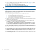
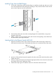
1. Locate the rail kit, part number 360332–003.
2. Install the two outer slide rails to the rack. The outer rails are marked “FRONT” and “REAR.”
On both sides of the rack, align the rail holes with the holes in the rack and secure with
thumbscrews.
3. Attach the inner rails to the sides of the node.
Align the holes in the rail with the round tabs on the side of the node and secure with
thumbscrews.
NOTE: The inner rails are identical.
The word “FRONT” should face away from the node, but will appear upside-down on one
side.
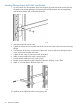
4. Align the rails on the node with the rails in the rack and slide the node fully into the rack.
If your rack contains single phase PDUs, you will install the node in rack position 35. If your
rack contains 3–phase PDUs, you will install the node in rack position 33.
5. Tighten the thumbscrews.
6. Repeat this procedure to install all of the nodes in the rack. See “NOTE” below for details.
16 Hardware Installation