
Technical data
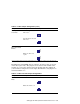

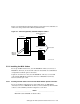
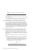
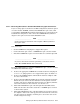
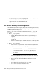
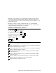
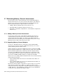

Table 5–2: MC2 Jumper Configuration (cont.)
Jumper: Description: Example:
J5: AlphaServer
8x00 Mode
8x00 mode selected:
Pins 1 to 2
a
123
8x00 mode not selected:
Pins 2 to 3
123
J10 and J11:
Fiber-Optic Mode
Enable
Fiber Off: Pins 1 to 2
3
2
1
Fiber On: Pins 2 to
3 pins
3
2
1
a
Increases the maximum sustainable bandwidth for 8x00 systems. If the jumpers are in this position for
other systems, the bandwidth is decreased.
The MC2 linecard (CCMLB) has two jumpers, J2 and J3, that are used to
enable fiber-optic mode. The jumpers are located near the middle of the
module (as you view the jumper side of the module with the endplate in
your left hand). Jumper J2 is on the right. The MC2 linecard jumpers are
described in Table 5–3.
Table 5–3: MC2 Linecard Jumper Configurations
Jumper: Description: Example:
J2 and J3: Fiber
Mode
Fiber Off: Pins 2 to 3
123
Fiber On: Pins 1 to 2
123
Setting Up the Memory Channel Cluster Interconnect 5–5