
Technical data
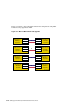
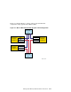
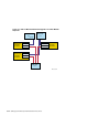
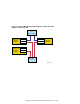
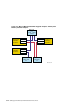

Table 5–4: Adding a Memory Channel Interconnect or Upgrading from a
Dual, Redundant MC1 Interconnect to MC2 Interconnects (cont.)
Step
Action Refer to:
MC2:
Hub mode — Standard hub mode or virtual
hub mode (VH0 or VH1)
• Virtual hub mode, VH0: Jumper pins 2 to 3
• Virtual hub mode, VH1: No jumper
• Standard hub mode: Jumper pins 1 to 2
J3 — Memory Channel address space: Select 128
MB (jumper pins 1 to 2) or 512 MB (jumper pins 2
to 3) as required for your configuration
______________________ Note ______________________
If you set the J3 jumpers for 128 MB because the other interconnect
is MC1, and then later on decide to upgrade to dual, redundant MC2
hardware using 512 MB address space, you will have to reset the
jumpers. If you set the jumpers to 512 MB now, the software will only
allow the use of 128 MB address space for a mixed rail cluster (MC1 on
one rail, MC2 on the other rail).
J4 — Page size: Jumper pins 1 to 3 to select 8 KB
J5 — AlphaServer 8x00 Mode: Jumper pins 1
to 2 for AlphaServer 8200, 8400, GS60, GS60E,
and GS140 systems and jumper pins 2 to 3 for
all other AlphaServer systems
J10 — Fiber Optics Mode Enable: Jumper pins 2 to 3
to enable the use of the fiber-optic modules. Jumper
pins 1 to 2 to disable the use of fiber optics
5
If adding a Memory Channel interconnect: Install
the Memory Channel adapter module.
Section 5.2 and
Memory Channel
User’s Guide
If this is the second system in a virtual hub
configuration, connect an MC1 or MC2 link cable
between the MC1 or MC2 modules.
For a standard hub configuration, use a link cable
to connect the adapter to the Memory Channel hub
linecard in the hub slot that corresponds to the existing
Memory Channel linecard in the other hub.
If upgrading from a dual, redundant MC1
interconnect to MC2 interconnects: Remove the
MC1 adapter and install the MC2 adapter.
5–16 Setting Up the Memory Channel Cluster Interconnect