
Technical data

1, which enables failover pair. See the Cluster Highly Available
Applications manual for more information.
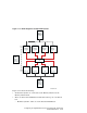
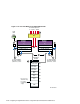
Figure 11–2 provides a detailed illustration of the first two systems in an
8-node shared SCSI cluster. Table 11–1 lists the components that are used to
create the portion of the cluster that is shown in Figure 11–2.
To install the cluster hardware for the first two member systems of an
eight-node cluster, follow these steps:
1. Install Memory Channel adapters on member systems 1 and 2. See
Chapter 5 for installation and jumper information on the Memory
Channel adapters. Delay testing the Memory Channel until you have
installed all hardware.
2. Install a Memory Channel hub within 10 meters (32.8 feet) of all eight
member systems.
3. Use BN39B-04 (4 meters; 13.1 feet) or BN39B-10 (10 meters; 32.8 feet)
to connect the Memory Channel adapters of member systems 1 and 2 to
the Memory Channel hub.
4. Refer to the hardware manuals and install the network adapters for the
public network on member systems 1 and 2. The public network is not
shown in the illustrations in this chapter.
5. Refer to Table 9–3 and install two KZPBA-CB host bus adapters on
member system 1 and 2 for the shared SCSI buses that they will use:
• A shared SCSI bus for member system 1 and 2.
• A shared SCSI bus for member system 2 with member systems
3, 4, and 5.
• A shared SCSI bus for member system 1 with member systems
5, 6, and 7.
Ensure that you set the host bus adapter SCSI IDs as follows:
• Member system 1: SCSI bus ID 7 (for both host bus adapters)
• Member system 2: SCSI bus ID 6 (for both host bus adapters)
6. Ensure that each system (member system 1 and 2) has a BN21W-0B Y
cable attached to each KZPBA-CB host bus adapter and an H879-AA
HD68 terminator attached to one leg of each BN21W-0B Y cable.
Member systems 1 and 2 will be at one end of each of the two SCSI
buses they share.
11–6 Configuring an Eight-Member Cluster Using Externally Terminated Shared SCSI Buses