Datadoc - DEC/VAX 7xx0/10xx0 This section by Dave Bazley..... Revision: Written July 1993, updated January 1994, August 1994, April 1995. 1 Introduction This section contains information on the following systems: DEC7xx0, DEC10xx0, VAX7xx0 and VAX10xx0.
Sources of information 2.1 Training You need to be trained to work on these systems. The VAX 7000 is not "just like a VAX 6000". The only common part is the XMI, which is used only for I/O and has a different backplane, power supply and options. The other 7000/10000 systems are entirely new. The following courses are available on TIMA or from EDU in your local OLC: Table 1: Current training Course Name Course No.
2.2 Documentation The following manuals are available on Fiche and TIMA. A selection of these manuals can also be found in the Welwyn Technical Library. Some are grouped into kits. The Hardware User Information kit and the Installation kit are supplied with each system, so you should find these manuals on site. The kits are listed in the first table. The next 3 tables list individual manuals for DEC 7000/10000, DEC/VAX 7000/10000 and VAX 7000/10000. In each case the 7000 (only) manuals are listed first.
• DEC7000/10000 AXP Technical Bulletin No 2, E*-70TBA-T2-A01, (TIMA/Fiche) Contains: Update information to accompany the release of DEC OSF/1 AXP V1.3. Covers booting, using VET and servicing the MS7BB. • Alpha AXP Systems Handbook , (Sales Library) Customer book telling all about Alpha AXP. Some interesting stuff on 7000/10000 and other AXP systems. Also covers the chip, the architecture, and some new network and storage products. • KN7AA CPU Installation Card , EK-KN7AA-IN-001.
• DEC7000 AXP/VAX7000 Removable Media Install Guide , E*-TFRRD-IN-001, (TIMA/Fiche) Describes installing and testing a TF85 or RRD42 in a system or expander cabinet. • DEC7000 AXP/VAX7000 Site Preparation Guide , EK-7000B-SP-002 (TIMA) Contains: Cabinet size and weight, floor space, environmental and power requirements. • DEC7000 AXP/VAX7000 System Service Manual , E*-7002B-SV-002, (TIMA/Fiche) Contains: Replacing/adding CPUs and memories, CPU setups, using the LFU.
2.2.4 VAX 7000/10000 Manuals • VAX7000 Pocket Service Guide , E*-7000A-PG-001, (TIMA/Fiche) Contains:Registers, addressing, some console commands, testing, FRUs, controls and indicators, errors, LFU and ROM information. • VAX7000 Advanced Troubleshooting , E*-7001A-TS-001, (TIMA/Fiche) Contains: Powerup and self test with LEDs and console display, diagnostics, parse trees and PSU info. Written for engineers. • VAX7000/10000 Technical Bulletin Number 4, EK-70TBA-T4.
• DEC10000 AXP/VAX10000 Operations Manual , EK-1000B-OP-002, (TIMA/Fiche [See kits]) Contains: Description of systems, options, controls and indicators, booting, some console commands and LFU information. • DEC10000 AXP/VAX10000 Basic Troubleshooting , EK-1000B-TS-002, (TIMA/Fiche [See kits]) Contains: Power up and boot flows, self test info., SHOW and TEST commands, indicators. Written for operators.
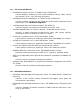
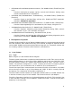
A TF85 (for VAX systems) or RRD42 (for DEC systems) can be fitted, as an optional load device. They connect to the XMI via a KFMSA or KZMSA. Figure 1 shows some XMI adapters, for a full list see Section 4, XMI Supported Options . 3.1.2 Packaging Refer to Figure 2, Laser Platform System Cabinet Layout . The Laser platform system cabinet is slightly wider and taller than a VAX6000 cabinet. This means you cannot install one in an existing line of VAXes without moving them.
Figure 1: Laser Platform BLock Diagram C P U C P U / M E M C P U / M E M C P U / M E M C P U / M E M C P U / M E M M E M M E M LSB Hose 2 Hose 0 Hose 3 I O P Hose 1 LAMB FLAG CLOCK CI CIXCD NI DEBNA DSSI KFMSA DEFAA X M I See Note 1 F U T U R E B U S TF85 NOTES: 1. XMI = 14 slots.
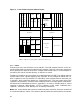
Figure 2: Laser Platform System Cabinet Layout F I L T E R S TF85 C P U OCP C P U C P U C P U or or or 48v 48v 48v M E M M E M M E M Reg Reg Reg L D C C C L M E M A/C I/P Box Laser System Bus Power System Power System Air Mover XMI PIU XMI Reg I O Power Distribution C P U C P U or or or M E M M E M M E M Laser System Bus Air Mover Disk PIU XMI Reg C P U Disk Another PIU XMI PIU Disk Futurebus+ Disk Disk or (See note 1) Storage Disk Disk XMI FRONT REAR N
The console is able to monitor the H7263 regulators and the air mover via the CCL. Thus the status of the power system can be displayed on the console. Future implementations may even extend to errorlog packets being provided for the Operating System! 3.1.4 System Modules Here is a brief summary of current Laser system modules. Note that there are two sorts of CPU Module, one for the VAX7000/10000, and one for the DEC7000/10000 AXP. This is the only real hardware difference between the VAX and AXP systems.
• • DEC 7700/10700 AXP CPU Module + Called KN7AB + Based on 21064A, EV4_5 Alpha RISC chip + 275 MHz clock, ~50% faster than KN7AA + Cannot be mixed with KN7AA + Part No. = E2057-AA Primary (boot) CPU must reside in slot 0 (LHS, front) of LSB 3.1.4.2 Memory Modules • 64 MB Memory Module (MS7AA-AA), Part no. = E2043-AA • 128 MB Memory Module (MS7AA-BA), Part no. = E2043-BA • 256 MB Memory Module (MS7AA-CA), Part no. = E2043-CA • 512 MB Memory Module (MS7AA-DA), Part no.
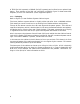
Figure 3: Laser Expander Cabinet Layout C C L 48v 48v 48v Reg Reg Reg Storage only Power Distribution Storage only A/C I/P Box Storage PIU Power System Power System Air Mover Storage PIU Air Mover Another PIU Another PIU XMI XMI or BI or or Storage Storage or or Battery Battery Another PIU Another PIU Futurebus+ Futurebus+ or or Storage Storage (See note 1) (See note 1) FRONT REAR NOTES: 1. XMI, BI and Battery PIUs use the full depth of the cabinet. 3.
The cabinet space filled by a PIU is known as a quadrant (’cos 4 can fit in the bottom of a cabinet). However, XMI, VAXBI and battery PIUs take up 2 quadrants (1 front and 1 rear) each. This means that only 2 of these PIUs can be fitted in a cabinet. The Futurebus+ and Storage PIUs only take up 1 quadrant and thus 4 can be fitted in the system cabinet and 6 in the expander. Each PIU is briefly described below.
3.3.3 Futurebus+ PIU Only supported on DEC7000/10000 systems. The Futurebus+ PIU houses a Futurebus+ card cage and regulators. It occupies 1 (lower, rear) PIU quadrant. A maximum of 2 per cabinet and 3 per system is allowed (1 XMI must be present). The Futurebus backplane has 10 slots. Slot 5 contains the FLAG module, leaving 9 slots for I/O. See Section 5 for a discussion of the Futurebus+ itself. 3.3.4 SCSI Disk and Tape PIU Only supported on DEC7000/10000 systems.
3.4 Who’s who of 7000/10000 systems This table lists the 7000 and 10000 systems currently available.
4 XMI Supported Options The following tables list current supported XMI options for DEC 7000/10000 and VAX 7000/10000 systems. Table 3: DEC 7000/10000 - XMI Options Adapter type Max per XMI (OVMS) CI 2 DEMFA FDDI LAN 4 4 4 8 1.4 [0514] DEMNA NI LAN 4 4 4 8 8.02 [0802] KDM70 RA/TA/ESE 3 12 3 6 3.00 [1E11] KFMSB DSSI 6 6 SCSI 4 6 Option CIXCD ! # KZMSA $ ! " # $ Max per System (OVMS) Max per XMI (OSF) Max per System (OSF) 1 Min firmware rev 1.0 [0111] " 1.0 8 8 4.
4.1 Unsupported XMI options The following XMI options are not supported on DEC/VAX 7000/10000 systems. Be careful if upgrading from a 6000 to a 7000, you cannot tranfer these modules. Option Adapter type Module Comment CIXCD CI T2080 Use CIXCD-AC (T2080-YA) DWMBA BI T2012 Old BI adapter, use DWMBB DWMUA Unibus KFMSA-AA DSSI Mythical XMI to Unibus adapter? T2036 Old DSSI adapter, use KFMSA-BA 4.
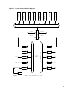
On DEC 7000/10000 systems Futurebus+ Profile B is used as an I/O bus. A brief description of the hardware involved is given below. For a detailed explanation see the DEC 7000 AXP/VAX 7000 I/O System Technical Manual. For more on concepts do CBI (see Section 2.1, Training ). 5.2 Hardware See Figure 4, Generic PIU Layout The Futurebus+ consists of a 10 slot backplane and card cage, plus regulators. These make up the Futurebus+ PIU. Slot 5 is dedicated to the DWLAA (aka. FLAG) module.
6.1 Current versions Current (and old) versions of consoles you may meet are listed below along with some of their "features". Please read the individual release notes for more details. I have included their locations in case you need a particular version in a hurry. A copy of the latest version is kept in the Datadoc Media Cupboard for those of you at Newmarket and Welwyn. 6.1.1 DEC versions • Really OLD ones, don’t use these, they are just listed for completeness: V2.1, V2.4, V2.5, V3.0, V3.1, V3.
• DEC 7000/10000 V4.4 CD: Alpha AXP System Firmware Update V3.4, part no: AG-PTMWR-BE LFU image called AXP7000_V10 Available from VESDAT::DISK$PUBLIC: Required for OVMS V7.0 and UNIX V4.0 No bug fixs since V4.3 update -e no longer supported • DEC 7000/10000 V4.5 CD: Alpha AXP System Firmware Update V3.5, part no: AG-PTMWS-BE LFU image called AXP7000_V11 Available from VESDAT::DISK$PUBLIC: Supports OVMS V7.0 and UNIX V3.2d or V4.0 PALcode = V5.53-3 for VMS, V1.
• VAX 7000/10000 V3.1 Minor upgrade to V3.0, not released on CD Controller-based shadow set problem (ds.. in BOOTDEF_DEV) fixed Console now recognises all EFxx disk drives Available from PROXY"fal$access"::LASER_CONS_PUBLIC:[PUBLIC] VAX7000_V08.SYS (MOP-loadable LFU image) • VAX 7000/10000 V3.2 Minor upgrade to 3.2, not available on CD (after all) Contains fix for HSJ-40 reboot problem, plus fixes in V3.
Console CD part no: AQ-PQW1F-BE LFU image called VAX7000_V0A Available from VESDAT::DISK$PUBLIC: • VAX 7000/10000 V4.2 V4.1 power problems fixed New environmental variable, COMPAT_MODE, allows VAX VMS V5.5-2 to run on 7600s (in addition to 7800s) New environmental variable, BOOTVAX_COMPAT, allows reboots from initial boot device or BOOTDEF_DEV Console CD part no: AQ-PQW1G-BE LFU image called VAX7000_V0B Available from VESDAT::DISK$PUBLIC: VAX7000_V0B.EXE (local bootable LFU image) VAX7000_V0B.
The latest version of VAX LFU is V0B. This comes with console V4.0 and supports the following devices: Table 5: VAX7000_V0B LFU devices and revisions Device Hardware Rev. CD Firmware Rev. CIXCD All 72.0 DEMFA All 2.0 DEMNA All 8.3 KA7AA All 4.2 (76xx console rev.) † KA7AB All 4.2 (77xx console rev.) † KA7AC All 4.2 (78xx console rev.) † KCM44 All 3.1 KDM70 All 4.4 KFMSA A01 to A04 5.1 KFMSA B01 to B04 5.6 †Latest (Apr 96) console revision = 4.
7.1 Important considerations when using the LFU The LFU makes upgrading firmware on Laser platform devices fairly easy and safe, provided a few points are taken into account: 1. On most of the modules the firmware is stored in a Flash ROM. This is a serial device which has to be completely loaded every time, in one go. Therefore, the LFU update must not be interrupted. If it is, the module can be left in a completely unuseable and unrecoverable state. If this happens it has to be replaced.
7.2.1 Booting the LFU from the console RRD42 This is the simplest method, but is restricted to DEC 7000/10000s as (normally) only these have RRD42s. As the "Alpha AXP Systems Firmware Update CD" has code for all Alpha systems on it, you have to specify the bootfile. 1. Load the Update CD into the console RRD42 2. At DEC 7000 >>> boot -flag 0,80 dkxn.n.n.n.n do >>> show device kzmsa* to find device name 3. After the initial bootstrap has loaded, you are asked for the Bootfile 4.
7.2.3 Booting the LFU from another system The latest Infoservers do not have a system disk so the procedures described in Section 8.2 are no use. The only way to load a "network copy" of the LFU in this situation, is from another system somewhere on the network: 1. Copy the appropriate .SYS file (VAX7000_Vnn.SYS or AXP7000_Vnn.SYS) into the MOM$LOAD directory of the chosen system. You will find this directory on any system which is setup to downline load Decservers etc. 2.
5. A number of services will be displayed, depending on how many Infoservers are present and how many services they offer 6. Select the one called "VAX7000_V07" 7. The LFU is loaded and it’s banner and menu appears 8. If you wanted to load something else, you could choose a different service at step 6. 8.1.2 Booting OpenVMS VAX Standalone BACKUP Here is an example of loading Standalone BACKUP from the OpenVMS VAX distribution CD. 1. Load CD into Infoserver 2.
2. At the Infoserver: † • Create partition on system disk for console image: INFOSERVER> Create partition dk1:VAX7000_Vnn blocks NNNN † INFOSERVER> Show partition dk1: • Create temporary service for this partition: INFOSERVER> Create service temp1 for dk1:VAX7000_Vnn 3. At the VAX: • Use BACKUP to unpack the saveset into SYSMAINT.
8.2.1 Booting the LFU from the Infoserver system disk Once the LFU image is on the Infoserver system disk (see Section 8.2), it is booted as follows. This is slightly different to booting from the console CD in that the Initial System Loader is not used.
10 Parts and FRUS The following tables are from the Product Service Plans. If you can’t find a part here look in the IPB.
Table 9: Futurebus+ PIU parts (AXP only) Part Number Mnemonic Description B2003-AA B????-?? 30-36009-01 30-36011-01 54-21662-01 DWLAA DEFAA FLAG module (Laser to FBUS+ ) FBUS+ to FDDI Module B (PWR), Fbus+ regulator Module A2 (PWR), fbus+ regulator FBUS+ Backplane Assy Table 10: Disk PIU parts Part Number Description RZ35-E0 54-19110-01 54-19119-01 54-20868-01 54-21664-01 54-21664-02 70-28814-01 RZ35 Disk Drive (SCSI) RZ73 Module RF73-EA ECM Module Local Disk Convertor Disk Control Panel (DSSI) Dis
Table 12 (Cont.
The Pocket Service Guide explains some console commands for testing. For more detail see Console Reference Manual. For LEDs and selftest failures see Advanced Troubleshooting Manual. Testing under the Operating System can be done with UETP for VAX systems and VET for DEC systems. See Section 14.2.4, DEC Verifier and Exerciser Tool (DEC VET) . 12 Troubleshooting Tips If you replace a CPU, in a multi-CPU system, use the LFU not the console UPDATE command to update the console firmware. See Section 7.
13 FCOs Table 13: FCO summary for DEC/VAX/7000/10000 FCO SB# Description 7xxx-F001 747 Removing C49 from blower servo stops it self-destructing Quick Check: blowers with serial nos. above 675 or marked with green dots are OK Kit: EQ-01656-01 7xxx-F002 751 New door catches + air pressure switch on CCL bypassed Quick check: door catches at rev D01 and CCL at rev J03 or greater are OK Kit: EQ-01666-01 7xxx-F003 758 Various power parts and cables upgraded to ensure FCC Compliance.
14 Known Features, Restrictions and Problems 14.1 Console issues These are some of the known console issues which might touch an MCS engineer. There are others, so always read the release notes for the version of console you are dealing with. 14.1.1 BOOTDEF_DEV restrictions VAX7000/10000 V1.2 console hangs during boot if string for BOOTDEF_DEV is greater than 96 characters. V2.4 supported up to 127 (thus allowing 6 devices to be specified), other environmental variables were limited to 31 characters.
14.1.4 DEC 7000 console V3.2 and OpenVMS AXP V1.5 Depending on CI and disk numbers, OpenVMS AXP V1.5 may not boot after the console has been upgraded to V3.2 or higher. The fix is to install a patch to OpenVMS before upgrading the console. The patch is on the Alpha AXP System Firmware Update CD, and called [DEC7000]AXPAPB01_ 015.A. Install it using VMSINSTAL. 14.1.5 HALT-RESTART problem in VAX V2.x and DEC V2.
Script> ^z >>> >>>show eeprom script powerup Powerup Script: d 27021 49a2108a d 271a3 49a2108a #close script (control Z) #print eeprom script #verify that it is correct At this point only the primary processor contains the change. Use the update -e command now to update the other CPUS, if present >>> init #initialize system Any HSCs which were reporting the EDC errors need to be re-booted to clear corruption in the data buffer descriptor. 14.1.
14.1.10 VAX 7000 and HSJ40, Single Path Booting Problem As described in Section 14.1.11, a VAX 7000 will not boot from an HSJ40 disk if one path to the HSJ40 controller is disabled. Unfortunately, this configuration is needed as a workaround for the HSJ40 "dual receive crash" problem. The following console patch allows the VAX 7000 to boot over a single path. It should only be installed on systems that boot from an HSJ40 system disk and have console version V3.24041[A6] .
14.1.12 DEC/VAX 7000 MOP booting problem Current DEC/VAX 7000 consoles cannot handle MOP Protocol V4. If there is a server anywhere on the network which supports V4 Protocol, the MOP boot may fail. Here is an example, seen while booting from an Infoserver 1000: >>> Booting... Connecting to boot device exa0 Created device: exa0.0.0.1.0 Requesting MOP Assistance Volunteer. MOP Assistance Volunteer found. Loading... .Retrying MEM_LOAD...Retries exhausted.
Environmental variables can still be manually set and the default ">>> boot" will work. However, there is something wrong with the EEPROM, and this can be fixed with a ">>> build eeprom"; after this the MOP boot will be ok. Note: ">>> build eeprom" causes customer environmental variables to be lost so note them first using ">>> show *" . 14.1.15 TEST DWLMA* fails on VAX 7000s with multiple XMIs This failure may occur on VAX 7000 systems with 2 x DWLMAs connected as dwlma0 and dwlma1.
14.1.17 Using wrong LFU can render CPU unusable You must use the correct LFU for the model being upgraded, See Blitz TD 1858. Basically for: DEC7000 Model 700, must use AXP7000_V0B or later VAX7000 Model 700, must use VAX7000_V08 or later 14.1.18 VAX7000-8XX Initialization problem At console V4.2, 78x0 CPUs in multiple CPU systems may fail to initialise. Do not replace CPU, just try again. May be fixed in future console FW release, see Blitz TD 1959. 14.2 Software issues 14.2.
14.2.2 Operating system .vs. firmware support + PALcode This table shows which version of console firmware is required for different versions of OpenVMS AXP and OSF/1, plus PALcode on DEC 7000/10000 systems. Console Rev LFU OpenVMS AXP DEC OSF/1 AXP PALcode 2.5 AXP7000_V07 1.5 1.2, 1.3 5.41-5/1.28-9 3.0 AXP7000_V08 1.5 1.3, 1.3A, 1.3B 5.44-1/1.32-3 3.1 AXP7000_V09 1.5 1.3, 1.3A, 1.3B, 2.0 5.47-1/1.34-2 3.2 AXP7000_V0A 1.5, 6.1 1.3, 1.3A, 1.3B, 2.0 5.48-1/1.35-1 4.
14.2.3 VAX 7000 systems may not reboot or write the dump file VAX 7000 systems using Host Based Volume Shadowing may display the following message during booting: "SHADOW-I-VOLPROC, DSAnnn does not contain member named to VMB, Warning system may not reboot or dump". If a bugcheck or forced crash occurs the system halts and a system dump is not written. This problem only occurs if CSCPAT_0269021 (patch including SHDRIVER) is installed. Fix is to obtain newer version of SHDRIVER from CSC. 14.2.
+ Enter AXP boot file : dka100:[VMS$COMMON.SYSEXE]APB.EXE The above will put the required good stuff in block 0 of the system disk. However, you will notice that OpenVMS has to be up, which could be a bit of a problem if you can’t boot the system disk! If the problem is not spotted until the system/cluster is all down, one of the following options may be your only hope: a. Boot Standalone Backup (from a CD). b.
14.2.9 OpenVMS AXP and DEC7000 Crash Dump Problems There are two situations on DEC7000 systems running OpenVMS AXP V6.1 which may cause only partial crash dumps to be written that are no use for analysis: On systems with large (512MB+) memories, booted from a system disc via the CI, writing the dump may stop prematurely with "Halt Code 05". This is caused by a bug in PNBTDRIVER.EXE. The fix is to apply the following patch kit: OpenVMS AXP patchkit, AXPBOOT01_061, available as CSCPAT_2091.
First errorlog is - ADAPTER ERROR KA7AA-AA XBER contains - Enable More Protocol & Write Error Interrupt & Error Summary Second errorlog is - MEMORY CONTROLLER ERROR KA7AA-AA 14.3.5 CCL capacitor backwards A bunch of systems left AYR between WK21 and WK31 of 1994 with capacitor C14 on the CCL module reversed. Most of these systems have been traced by DECnumber, so I mention it here just in case one or two slip through and cause subsequent problems.
14.3.9 EF51R-LA and EF52R-LA Disks VAX 7000/10000 Systems Early KA7AA/E2045 console code does not support the EF51R and EF52R DSSI drives. Fixed in version 3.0 of console. The hole around the Node-ID connector on the EF51R and EF52R drives does not allow the cable to be installed properly. (You have to "gently push" it). VMS V5.5-2 does not support ERF (Error Formatter) for the EF51R and EF52R disk drives. VMS V6.0 does. 14.3.
14.3.14 Vital information in Laser Errorlogs There is a process whereby Operating System errorlog information can be placed in the EEPROMs of Laser CPUs. These logs (called rather confusingly SDD) are a great help to the repair centres. This process was not supported by VMS before version 6.0 and OSF/1 version ???. So the message is: include a hardcopy of the errorlog with any CPU module you return (always a good idea anyway). 14.3.15 LFU Version 5.2 revision reporting The SHOW command under version 5.
Table 15: Minimum system revisions for PRESTOSERVE support DEC7000-600 DEC10000-600 CPU Module: E2040-AB Rev A01 E2040-YA Rev C01 PRESTO Memory: E2049-AA Rev C03 same Console: V3.0 same OSF: V1.3-4 same 14.3.20 DEC/VAX 7000/10000 Memory interleaving restriction A problem with the LEVI-A chip on early CPU modules results in the following memory configurations only being allowed.