User Manual V1.
CONTENT XAircraft MiniX Overview ............................................................................................................... 2 Products Specification ............................................................................................................ 2 MiniX Construction .......................................................................................................... 2 MiniX Features.........................................................................................
DISCLAIMER OF LIABILITY 1. Using XAircraft products within the limits permitted by local laws and regulations. XAircraft is not responsible for any illegal activities. 2. The MiniX is an aeromodelling product only. Please strictly follow the aeromodelling safe instruction rules; XAircraft are not responsible for the use and operation of the aircraft. 3. Model aircraft are not toys! Fly under professional guidance and strictly follow instruction rules in this document.
XAircraft MiniX Overview XAircraft MiniX is designed for multicopter, support 2 to 8 rotors. Products Specification MiniX Construction Flight Controller System The Flight Controller is the core of the system and is connected to GPS/compass and RC receiver for flight. It also has the black box flight data recording function which maintains the flight records for 40 minutes allowing users to view and share flight records.
XLINK GROUND STATION Includes XLINK AIR and XLINK GROUND modules. XLINK AIR is connected to the FC on the aircraft with XLINK GROUND connected to a computer, mobile phone or tablet to allow route planning by ground station. MiniX Features 1) Three flight modes supported: Manual ,ATT and GPS 2) ATT and GPS mode offers a high accuracy altitude hold. 3) More security options are available. For example the onboard failsafe can be preset for GO-home, auto landing/hover and can auto land at low voltage.
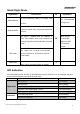
Working environment -10°C ~ 55°C Radio Configuration software Windows system ONLY Super Anti-Magnetic interference Bulit-in Black box support Configurable UVP support SBUS or PPMreceiver(normal types requires SBUS switch module)support Module Parameters: Product Voltage Weight Input Voltage : 7V~50.4 V FC (2S~12S) L:45.4mm 21.6g Output Voltage:5.8V,≤3A GPS 4.8V ~ 6.0V Dimension W:30.15mm H:17.43mm 17.5g Diameter:50.6mm H:16.2mm L:32.7mm OSD 4.8V ~ 6.0V 4.3g W:18.8mm H:9.
MiniX Interface PORT Function BAT Power,Li-Po battery(2S~12S, 7V~55V) S.BUS Receiver OUT(1,5) M1/M5 ESC(Black/white cable to M1,Red/Orange cable toM5) OUT(2,6) M2/M6 ESC(Black/white cable to M2,Red/Orange cable toM6) OUT(3,7) M3/M7 ESC(Black/white cable to M3,Red/Orange cable toM7) OUT(4,8) M4/M8 ESC(Black/white cable to M4,Red/Orange cable toM8) PORT Extension Module PORT Extension Module S.
MiniX Flight Mode Performance Flight Mode IO No Auto-Horizontal ability, no height hold Explanation Not recommended Manual Mode for beginners. function Auto-stabilize after sticks released. Height held Attitude Mode at throttle center. Pilot commands multirotors position. GPS signal is available with five satellites or more, auto-stabilize after sticks released and When M input M unconnected, enters GPS position hold.Height hold at throttle MINIX is in GPS center. ATT Mode by Default.
Firmware Upgrade Upgrading Green flashing System initialization or Self-check has failed(System can be Solid Red initialized in 10mins, it may take a little more in code weather Error Status System error: module communication failure or RC signal Red flashing incorrect. Strong interference of magnetic happens in GPS Mode. Weak signal or interference of Compass in GPS Mode. Yellow flashing MiniX Quick Guide XAircraft MiniX is an easy-to-use product. User can start to fly after few setups. 1.
Notes for Use Due to geographical limit and magnet influence on GPS module, please note: 1. Do not use GPS ATT Mode and Return to Home function in the areas which suffer from magnetic interference, for example, between buildings or indoor. 2. Do not use GPS ATT Mode and Return to Home function in polar region. 3. GPS module should avoid high voltage lines, and keep cables tidy around GPS. 4. When calibrating the compass, you do not have any electronic or magnetic objects such as cell phones.
Flight Controller installation notice: 1. Should be installed in cg position on copter. 2. Should pay attention to install direction, the triangle points to the head of copter. GPS module installation notice: 1. Horizontal install, higher than other electronic equipment. 2. Should pay attention to install direction, the triangle points to the head of copter. 3. Close to Flight Controller. 4. Far away from motor and other electric equipment.
When you see this removable device, it means MiniX is connected to the Computer. 1. Configuration software of MiniX is green software. Just need to run the MiniX.exe file to open it. Warning: Do not change any file in in the MiniX directory.
Supports all kinds of copter types, and custom types. According to copter and ESC you are using; choose correct Frame and ESC type. UltraPWM ESC: for original XAircraft UltraPWM ESC, for X450, X450 Pro, X650 and X650 Value. Notice: in the following diagram, the arrow direction means to rotation direction of motor and blade. When you install propeller, please make sure its direction downward. Quadcopter(X and + Style) ©2013 XAircraft All Rights Reserved.
Hexacopter(X, + and Y6) Notice: The outer-race motors are top-motors M1, M3 and M5 of Y6 copter; inter-race are bottom-motors M2, M4 and M6. Octacopter(X, + and X8) Notice: The outer-race motors are top-motors M1, M2 M3 and M4 of X8 copter; inter-race are bottom-motors M5, M6, M7 and M8. Calibration Mode Compass Calibration Please make sure GPS wiring and all the channels set up properly in your RC transmitter. Cancel all trims on radio before calibration and throttle stick down.
Copter stays horizontal Revolving slowly until slow green LED flashing Then vertically rotate until solid green, show as below: Copter side up Rotate slowly until LED solid on Compass Calibration completed when re-power on. Notes for Use Do not use GPS ATT Mode and Return to Home function in the areas which suffer from magnetic interference, for example, between buildings or indoor .
RC Neutral Point Calibration Cancel all trims on radio before calibration. Rapidly flick the Flight Mode Switch until LED is flashing Purple. Throttle up to neutral point, Led green-green flashing, show as below Release stick as shown and rapidly flick the Flight Mode Switch until solid green from LED.
Motor Start / Stop Follow diagram as below: Push sticks both toe-in or toe-out to start motors, then motors are running slowly. If the motors do not start after the operation, please check wiring of receiver and reverse setting of radio. Motor will stop under conditions below: 1) After motors started, if there is no pushing throttle in 3 seconds, another down-inside/down-outside operation can stop the motors immediately. 2) When copter already landed and throttle down to lowest, motors stop immediately.
neutral point than neutral point than neutral point During a fast cruise flight, copter height variance is normal due to the varying pressure. Attitude Gain When copter payloads or power changed, or using different frames, you will need to adjust attitude Gain to profit stable flight. Attitude Gain is divided into two parts, Basic Gain and RC Gain: 1. Basic Gain: needs to be set in software. A knob (RC Gain Input) adjusts the attitude gain based on this basic gain. 2.
The Gain value from RC is saved after landing. Thus, if you disconnect the Gain input, MiniX will continue use the last RC Gain to control the copter. Under Voltage Protection (UVP) Please select UVP protection in configuration software MiniX can detect the capacity of Li-po battery digitally when your battery is in good condition. 1. When voltage drops below3.6V the LED flashes Red-Red-Red. This is your low voltage warning. 2. If lower than 3.
1. Return to home and landing(tail in): copter turns its tail towards home (H) and then lifts up to 15m height (relative home point H), then returns to home and land. 2. Return to home and landing (nose in): copter turns its head towards home (H) and then lifts up to 15m height (relative home point H), then returns to home and land. This option is suitable for FPV. 3. Hovering: Copter will hold its position and wait for your control. 4. Landing: Copter will auto-land when the Safe Mode is activated.
About Home Position 1. If GPS has good signals before take-off, the home position is the place where motors started. 2. If GPS no signals before take-off, the home position is the place where GPS gets enough satellites to work. Get Back the Control If the RC Signal is normal, turn off the Safe Mode by switch, you will get back the control of flying immediately.
MiniX OSD Module System: choose corresponding video system according to your camera equipment. Attitude Line Style FPV Style: For the first-person view, the horizon on the screen refers to the real horizon. Gimbal Style: The horizon on the screen reflects the attitude angle of aircraft. Low Battery Alarm: When the battery voltage is lower than configured voltage, OSD raises the alarm.
OSD Diagram on Screen 1. Number of Satellite: The number of satellite that GPS has picked up. There are 10 satellites in the diagram. 2. Battery Voltage: The voltage of battery. The diagram shows that the battery voltage is 14.3V. 3. Horizontal Velocity: The present velocity is 0.1m/s in the diagram. 4. Flight Mode: It may show M-Manual Mode, A-Attitude Mode, S-Safe Mode, G- GPS Attitude Mode or W-Waypoint Mode. The present status is GPS Mode in the diagram. 5. Throttle: It’s 50% throttle in the diagram.
Firmware Upgrade and Configuration Software Update Upgrade Firmware 1. Connect MiniX to Computer. 2. Copy Firmware file (.xfw document) to root of removable disk “MINIX”, as diagram shows. 3. Eject MiniX disk. 4. Repower on MiniX Flight Controller, MiniX will auto upgrade Firmware. 5. After LED altering green-red flashing, firmware upgraded done. Upgrade Configuration Software When MiniX firmware is released, related configuration software also is updated.
Flight Controller Information and Language The FC ID is a unique number for this Flight Controller, please keep it in secret. ©2013 XAircraft All Rights Reserved.
XAircraft MiniX After-sale Service 1. Warranty Items 1) XAircraft provides a manufacturer's warranty on electronic parts caused by non-accident error or non-human error. It doesn't include the non-electronic parts like cover, wires and so on. 2) The warranty period is 6 months from the date of purchase. 3) During the warranty period, XAircraft will repair or replace for free within the warranty scope. 2.
XAircraft or global distributor/seller will contact you to confirm whether it's satisfied for you. For the repairable parts you can choose to replace under the range of warranty scope; otherwise we have to declare as a disabled product while beyond the warranty range. 5. 1) Shipping Fee Users in China Mainland have to pay for the return shipping if XAircraft product has a performance failure during the warranty items. Beyond the warranty items users have to pay for the shipping fee out and back.
support@xaircraft.com http://www.xaircraft.com Guangzhou JiFei Electronics Technology Co., Ltd (XAircraft) has the final power of interpretation on this manual. ©2013 XAircraft All Rights Reserved.