© Copyright 2009 Compex Systems Pte Ltd All Rights Reserved This document contains information, which is protected by copyright. Reproduction, adaptation or translation without prior permission is prohibited, except as allowed under the copyright laws. Trademark Information Compex® is a registered trademark of Compex, Inc. Microsoft Windows and the Windows logo are the trademarks of Microsoft Corp. NetWare is the registered trademark of Novell Inc.
FCC NOTICE This device has been tested and found to comply with the limits for a Class B digital device, pursuant to Part 15 of the FCC Rules. These limits are designed to provide reasonable protection against harmful interference in a residential installation. This device generates uses and can radiate radio frequency energy and, if not installed and used in accordance with the instructions, may cause harmful interference to radio communications.
Declaration of Conformity Compex, Inc. declares the following: Product Name: Wireless Access Point with PoE Model No.: MMJ543 conforms to the following Product Standards: This device complies with the Electromagnetic Compatibility Directive (89/336/EEC) issued by the Commission of the European Community. Compliance with this directive implies conformity to the following European Norms (in brackets are the equivalent international standards.
Table of Contents Overview the Product ..................................................................................................7 Introduction..................................................................................................................7 Features and Benefits ................................................................................................................8 Operation Modes and Connection Examples .....................................................................
System Tab..................................................................................................................58 Firmware Upgrade ..................................................................................................................58 Host Name ..............................................................................................................................59 Administrative and Read-only Account ...........................................................................
Overview the Product Introduction The high-performance Wireless Network Access Point (AP) is designed for enterprise and public access applications. Embedded with the Atheros chipset, it boasts network robustness, stability and wider network coverage. Based on 802.11n (Draft 2.0), the access point supports high-speed data transmission of up to 300Mbps.
Features and Benefits Point-to-Point & Point-to-MultiPoint Support Point-to-Point and Point-to-MultiPoint communication between different buildings enables you to bridge wireless clients that are kilometres apart while unifying the networks. Virtual AP (Multiple SSID) Virtual AP implements mSSID (Multi-SSID) This allows a single wireless card to be set up with multiple virtual AP connections with different SSIDs or BSSID (Basic Service Set Identifier) and security modes.
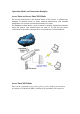
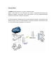
Operation Modes and Connection Examples Access Point and Access Point WDS Mode The Access Point Mode is the default mode of the device. It enables the bridging of wireless clients to wired network infrastructure and enables transparent access and communication with each other. The illustration below shows a typical resources sharing application example using this device. The wireless users are able to access the file server connected to the switch, through the access point in Access Point Mode.
Station Mode In Station mode the device acts as a wireless client. When connected to an access point, it creates a network link between the Ethernet network connected at this client device, and the wireless Ethernet network connected at the access point. In this example the workgroup PCs on the ethernet network connected to the Station device can access the printer across the wireless connection to the access point where the printer is connected.
Station WDS Mode Station WDS mode is similar to Station mode. The difference is Station WDS must connect to access point configured to Access Point WDS (or RootAP) mode. Station WDS is mainly use for point-to–point connection between 2 buildings or locations as far as several kilometer away. Point-to-Point An access point setup as Access Point WDS (or RootAP) and other as Station WDS (Transparent Client).
Router Mode In Router Mode, the device also operates as a router. Either the wireless or Ethernet can be setup as WAN connection to a broadband modem. Wireless as WAN is known as Station + Router mode (or Wireless Routing Client mode) and Ethernet as WAN is known as AP + Router mode (or Gateway mode). Device supports several types of broadband connections Static IP, Dynamic IP and PPPoE. For setup details refer to the respective section.
Repeater WDS Mode Repeater WDS Mode to mainly to extend the wireless range and coverage of the wireless network allowing access and communications over places generally difficult for wireless clients to connect to the network. In Repeater mode, the access point acts as a relay for network signals on the network by regenerating the signals it receives, and retransmitting them to main network infrastructure. Detailed information on the Repeater mode is available in the Repeater Setup section.
Device Panel Views and Descriptions Features 1 POWER LED Status and Indications Static ON: Power is being supplied to the device. Off: Power is not being supplied to the device. 3 DIAGNOSTIC LED Flashing: During power-up. Goes OFF after device is up. (low) 2 3 4 5 6 7 8 LED10 (higher low) LED20 (lower high) (high) LED30 LED40 SIGNAL STRENGTH LEVEL INDICATOR ETHERNET LINK LED ETHERNET PORT SURGE Steady ON: Link is established between device and the network.
Install the Hardware This section will show you how to install the hardware of the access point. • Antenna Alignment The antenna alignment of the access point must first be considered to ensure that the signal is strong. • Installation Direction After considering the antenna alignment, the direction in which the access point is facing must be considered to ensure that the signal is actually being directed to the receiving end.
Antenna Alignment The physical environment of the antenna must be examined when aligning the antenna. Obstructions, available mounting locations, and other factors must be considered. Many objects such as forests, buildings, and hills, can obstruct the antenna, reducing the signal strength. The antenna can be installed at a height above such obstructions, and aligned so that antennas are directed at each other by taking into account the horizontal angle and the vertical angle of the antenna signal.
Installation Direction The directional antenna radiates the signal towards the front of the unit. The unit should be installed in a position whereby the front of the unit faces the direction you wish to send the signal to. Therefore the direction you wish to send the signal to has to be considered before going on to the next step of starting to set up the access point.
Setup Requirements • CAT5/5e Networking Cable. • At least 1 computer installed with a web browser and a wired or wireless network interface adapter. All network nodes installed with TCP/IP and properly configured IP address parameters. • Mount the Unit on a Pole Access point is designed to mount to a pole. The mounting method will be described as shown below.
Prepare Unit to mount to a pole Unpack the 2 cable ties from the box. Loop each cable tie through the mounting bracket hole at the top and bottom. Wrap them round the pole and tighten the cable ties to secure the unit to the pole. Connect one end of an RJ45 Ethernet cable to the LAN OUT port of the Injector and the other end to LAN of the access point. Maximum length of the RJ45 Category 5 cable is 100 meters*. * Up to 200mW radio. For higher power radio need upgrade to higher rating power adapter.
Connect the RJ45 Ethernet cable attached to the PoE Injector to a network device, such as to a switch or to the PC you will use to configure the access point. PoE power input: Passive PoE (range 12V – 24V DC) Connect the power adapter in the PoE kit to the main electrical supply and the power plug into the socket of the injector. Now, turn on your power supply. Notice that the POWER LED has lighted up.
Configure the IP Address After setting up the hardware you need to assign an IP address to your PC so that it is in the same subnet as the access point. For Windows 95/98/98SE/ME/NT Step 1: From your desktop, right-click the Network Neighborhood icon and select Properties. Step 2: Select the network adapter that you are using, then right-click and select Properties. Step 3: Highlight TCP/IP and click on the Properties button. Step 4: Select the Specify an IP address radio button.
Step 5: To verify that the IP address has been correctly assigned to your PC, go to the Start menu, select Run, and enter the command: winipcfg. Select the Ethernet adapter from the drop-down list and click OK. PC is now setup with proper IP address to communicate with the access point.
For Windows XP/2000 Step 1: Go to your desktop, right-click on the My Network Places icon and select Properties. Step 2: Right-click the network adapter icon and select Properties. Step 3: Highlight Internet (TCP/IP) and click Properties button. Protocol on the Step 4: Select the Use the following IP address radio button. Set the IP address to 192.168.168.X and subnet mask to 255.255.255.0, where X can be any number from 2 to 254.
Step 5: Click on the OK button to close all windows. Step 6: To verify that the IP address has been correctly assigned to your PC, go to the Start menu, Accessories, select Command Prompt, and type the command: ipconfig/all PC is now setup with a proper IP address to communicate with the access point.
Access the Web Interface Access with uConfig The UConfig utility provides direct access to the web interface. Step 1: Insert the Product CD into your CD-ROM drive, the CD will autorun. Step 2: From the Utilities section, select to install the uConfig utility to your hard disk. Step 3: After installation double-click on the uConfig icon and click on the Yes button.
Step 4: Select the access point from the products list and click on the Open Web button. To retrieve and display the latest device(s) in the list, click on the Refresh button. Step 5: Do not exit the uConfig program while accessing the web-based interface as this will disconnect you from the device. Click on the OK button.
Step 6: At the login prompt, enter the User Name and Password. The default are : User Name : admin Password : password Step 7: It then opens the device home page. The Status page.
Access with a Web Browser Step 1: Launch your Web browser. e.g. MS Internet Explorer, FireFox, Netscape, etc.. For MS IE, under the Tools tab, select Internet Options. Step 2: Open the Connections tab and in the LAN Settings section disable all the option boxes. Click on the OK button to update the changes. Step 3: At the Address bar type in http://192.168.168.1 and press Enter on your keyboard.
Step 4: At the login prompt, enter the User Name and Password. The default are : User Name : admin Password : password It then opens the device home page. The Status page.
Navigation Main Menu Bar Status : Page displays current status of the device and the statistical information. Basic Wireless : Page contains the controls for a wireless network configuration, while covering basic wireless settings which define operating mode, associating details and data security options. Basic Network : Page covers the configuration of network operating mode, IP settings and network services (i.e. DHCP Server). Advanced Wireless : Page settings for more advanced wireless features.
Basic Network Tab Click BASIC NETWORK from the menu bar to open the page as show below. Network Modes: Bridging and Routing Network Mode: Select between Bridge (default) and Router mode. LAN Setup LAN Mode: Static: (default) lets you enter a specific IP address for the device. Default IP address is 192.168.168.1 DHCP Client: when set let device learn the IP address automatically from the network. Netmask: Let you set the class for the IP address set. Default class C and value is 255.255.255.
Gateway: (optional) Enter the gateway IP address of the network the device is connected. Primary DNS IP: (optional) Enter the primary DNS IP address nearest to the gateway router. Secondary DNS IP: (optional) Enter the secondary DNS IP address nearest to the gateway router. DHCP Mode: None: function disabled DHCP Server: Check to enable. Device act IP address distribution server automatically issue IP address and other network information to the DHCP Client request them. DHCP Relay: check to enable.
Basic Wireless Tab Under the tab, there is the selection of 4 radios. Fig 2.1 Basic Wireless Tab Currently device support only one 802..11n radio card. Select RADIO 1 to configure. Basic Wireless Tab contains all the wireless setup, which is necessary for the operator to setup the wireless part of the link. Enable the radio Fig 2.2 Enable Radio Checkbox Tick/Untick the checkbox to enable/disable the radio. Basic Wireless Settings All the basic wireless settings can be configured in this page.
Wireless Mode There are 5 modes available. Access Point This mode can be connected to Station mode, and then forwards all the traffic to the network devices connected to the Ethernet devices of the Station. Access Point WDS This mode can be connected to Station WDS mode. Using WDS protocol, it allows a client or station device to bridge wireless traffic transparently. Station: This is a client mode that can be connected to the Access Point mode.
Access Point Parameters Settings Fig 2.3 Basic Wireless Settings (Access Point/ Access Point WDS) Local AP-ESSID This is the Service Set Identifier used to identify the operator’s wireless LAN. It should be specified while operating in Access Point or Access Point WDS mode. All the client devices within its range will receive broadcast messages from the access point advertising this SSID.
Channel Spectrum Width 20M represents the data transmitted at a bandwidth of 20MHz. 20/40MHz represents the data transmitted at either 20MHz or 40MHz. In very noisy environment it automatically fall back to 20MHz to be more resilient to the interference. In situation when auto fall back did not happened, manually changing channel spectrum width to 20MHz will to help reduce interference on the link and improve performance. * Note: 40MHz bandwidth is non-standard for 802.11n/g mode operation.
Station Parameters Settings Fig 2.4 Basic Wireless Settings (Station/Station WDS) This options below are only available in Station, Station WDS and Repeater WDS modes unless otherwise stated. Wireless Mode: Station Remote AP-ESSID This is the Service Set Identifier used by station to seek and connect to the access point of same the SSID identifier.
Channel Scan List Fig 2.5 Channel Scan List (In US Country Code) According to the availability of channels in the country codes, the operator can select which channels to be scanned when scanning for an Access Point. Then the scanned channels will appear on the Site Survey. Wireless Adapter mode This option change device function like a wireless adapter installed in a computer.
Wireless Security All the wireless security settings are set under this section. The operation of the Keys is the same for ALL the Wireless modes. WPA or WPA2 Authentication Fig 2.7 WPA (Access Point/Access Point WDS/Repeater WDS) WPA PSK PSK (Default) – WPA or WPA2 with Pre-shared Key method. Cipher Type TKIP - Temporal Key Integrity Protocol which uses RC4 encryption algorithm. AES - Advanced Encryption Standard (AES) algorithm. AUTO (Default) – Automatically select between both algorithms.
WPA + EAP Fig 2.8 WPA + EAP EAP – WPA or WPA2 with EAP (Extensible Authentication Protocol) Firmware supported options for clients are: EAP-TLS, EAP-TTLS, PEAP Cipher Type TKIP - Temporal Key Integrity Protocol which uses RC4 encryption algorithm. AES - Advanced Encryption Standard (AES) algorithm. AUTO (Default) – Automatically select between both algorithms. Primary Radius Server IP Enter the Primary Radius Server IP address . Secondary Radius Server IP Enter the Secondary Radius Server IP address .
WPA + EAP_TLS, WPA-TTLS, WPA-PEAP Fig 2.8 WPA (Station /Station WDS/Repeater WDS) This apply to the following modes only, when WPA or WPA2, with EAP is selected. Station, Station WDS, Repeater WDS mode. Identity Identification credential used by the wpa-supplicant for EAP authentication. User Name: Identification credential used by the wpa-supplicant for EAP unencrypted form.
IEEE802.1x Settings The operation of the Keys is the same for ALL the modes. Fig. 2.8 IEEE802.1X (Access Point/Access Point WDS/ Repeater WDS) This option apply to the following modes only, when WPA EAP or IEEE802.1x . Access Point, Access Point WDS, Repeater WDS modes. Primary Radius Server IP Enter the Primary Radius Server IP that Access Point will use to query server. Secondary Radius Server IP Enter the Secondary Radius Server IP that Access Point will use to query the server.
WEP Fig 2.6 WEP The operation of the Keys is the same for ALL the modes. ** Note: Operating with WEP security will lower the performance significantly with 802.11n radio. Not recommended for Access Point and Access Point WDS mode operation. May use WEP ONLY when connecting with standard 11 and 54Mbps (legacy) 802.11a/b/g bands radio. Authentication Type: Open Authentication – (Default) No authentication. Recommend to use this standard option over shared authentication.
Virtual Access Point (VAP) Virtual AP (VAP) implements mSSID (Multi-SSID) whereby a single wireless card can be setup with up to 3 virtual SSID of BSSID connections. Each VAP can be set with different security authentication mode. Fig 2.11 Virtual AP (Only Available in Access Point/ Access Point WDS Mode) All VAPs are created from the same radio they all share the same wireless channel, country code, channel spectrum width and transmit power.
Advance Wireless Tab Click Advanced Wireless tab from menu and select RADIO 1 to open the page below. Long Range Parameters Setup Advanced wireless page let you setup outdoor long distant connection parameters. Long Range Parameters: Check to enable parameters. Beacon Interval: (default is 100 ms) Define the time interval (in millisecond) the beacon to broadcast. Recommend to use default.
Noise Immunity: Check to enable. When enabled, it automatically adjusts the signal/noise level for best performance. In low noise environment it is recommended to turn off this function. Signal Strength Indicator (RSSI): The default values are LED1-Red (10), LED2-Yellow (20), LED3-Green (40) Each LEDs when turn on indicates the RSSI signal strength has hit over the value. e.g. When LED1 and LED2 light up it indicate the RSSI is greater than 20. When all 4 LEDs light up it indicate RSSI is greater than 40.
Advanced Network Tab Click Advanced Network tab from menu to open the page below. *Note: This tab will not open when in device is in Bridge node.
Spanning Tree Setup Spanning Tree Protocol: Default is disabled. Check on box to enable. Root Priority: Default value is 32768. Smaller value has higher priority. Root Hello Time: Default time is 2 seconds. Root Forward Delay: Default is 15 seconds Root Maximum Age: Default is 20 seconds Changing to lower time can caused high overheads to the network. NAT Setup NAT: Enabled when in Router mode. Disabled when in Bridge mode. DMZ: Default is disabled. Check on box to enable.
Adding an entry from Custom Server Entry from Custom Server box lets you enter the other port number service for an application and new applications. Custom Server also lets you enter a different public and private port service Server Type: Enter a brief name for the application. This info helps you track the application for that port number you set. Protocol: Select TCP or UDP the application use. Public Port: select Single or Range of ports application use. From: if single port, enter this box only.
Bandwidth Control Bandwidth Control: Default is disabled. Check on box to enable. This control let user set a max limited bandwidth to router. This function let use share one high speed broadband line with several routers each limited to a maximum limited by its bandwidth control. Download Total Rate(kbit) enter the max bandwidth limit for downloading on this router. Upload Total Rate(kbit): enter the max bandwidth limit for uploading on this router.
Firewall Setup Firewall Setup: Default is disabled. Check on box to enable. For configuration refer to Appendix section. Comment: enter a brief name for the service.
Outbound Filtering Setup Filtering Setup: Default is disabled. Check on box to enable. For configuration refer to Appendix section. DNS Redirection: Default is enabled. Check on box to disable. When enabled, router device will act as DNS proxy. PC connected to this router device to set their TCPIP DNS IP to router’s IP address. PC can still setup a valid DNS IP to skip the DNS proxy handling. Dynamic DNS Setup: Default is disabled. Check on box to enable.
UPNP: Default is disabled. Check on box to enabled. When enabled, client PC running Microsoft UPnP services can automatically open certain specific port required by the PC application in the router. For security reason this service should not be open. Recommend to setup manually open all port service through Port Forwarding service.
Services Tab Click Services tab from menu to open the page below. Services section provides varieties of useful and enhanced functions to help assist device operations.
Ping Watchdog Enable Ping Watchdog: Default is disabled. Check on box to enable. IP Address To Ping: Target IP address do ping test monitor. Ping Interval: Default is 5 seconds (minimum). This is Ping test duration. Startup Delay: Default is 60 seconds(minimum). One time delay after device startup. Failed Count To Reboot: Default is 5. This is the number of ping failure count before device kick in the reboot process. Auto-Reboot Auto-Reboot Mode: Default is disabled. Select By Hour or By Time check.
SNMP Setup Enable SNMP: Default is disabled. Check on box to enable. Read Only Password: Password to query device. Engine ID: Default is Enable SNMP Trap: Default is disabled. Check on box to enable. Trap Destination IP: Enter the IP to send the info when trap is triggered. Community: Enter the SNMP community string. NTP Setup Enable NTP Client: Default is disabled. Check on box to enable. Select Your Time Zone: Select from list the country you reside. Custom Time Server: Default is “time.nist.
Telnet Access Setup Enable Telnet Server: Default is enabled. Remove check on box to disable. Server Port: Default is 23. Enter new preferred port number. SSH Access Setup Enable SSH Server: Default is disabled. Check on box to enable. Server Port: Default is 22. Enter new preferred port number. System Log Setup Enable System Logging: Default is disabled. Check on box to enable. Logging IP /Domain Name: Enter destination IP address of device to receive log. Logging Port: Default is 514.
System Tab The System Page contains Administrative options. This page enables administrator to customize, reboot the device, set it to factory defaults, upload a new firmware, backup or update the configuration and configure administrator’s credentials. Firmware Upgrade Use this section to find out current software version and update the device with the new firmware. The device firmware update is compatible with all configuration settings.
Host Name Host Name is the system wide device identifier. It is reported by SNMP Agent to authorized management stations. Host Name will be represented in popular Router Operating Systems registration screens and discovery tools. Host Name: specifies the system identity. Change button saves the Host Name if activated. Administrative and Read-only Account In this section you can modify the administrator password to protect your device from unauthorized configuration.
Configuration Management Backup Configuration: click Download button to export the current configuration to a file. Upload Configuration: click Browse button to navigate to and select the new configuration file or specify the full path to the configuration file location. Activating the Upload button will transfer new configuration file to the system. New configuration will be effective after the Apply button is activated and system reboot cycle is completed.
Status Page The Status Page displays a summary of link status information, current values of basic configuration settings (depending on operating mode), network settings and traffic statistics of all the interfaces. Status Reporting Main Uptime: displays device up time since boot up. The time is expressed in days, hours, minutes and seconds. Host Name: displays the assigned device host name (ID). System Time: display device current date and time.
LAN Setting LAN MAC: displays the MAC address of the device LAN (Ethernet) interface. LAN Mode: displays the mode used, either static or DHCP client. LAN IP Address: displays the current IP address of the LAN (Ethernet) interface. LAN Gateway IP Address: displays the IP address of the gateway used in LAN. LAN Pri. DNS IP: displays the Primary DNS IP address of the LAN setting. LAN Sec. DNS IP: displays the Secondary DNS IP address of the LAN setting.
Station Connection Status Info Click at the bottom of the Status page to view client connection statistics. WLAN Connected Status: MAC Address: displays the MAC address of the current active WLAN card. Signal Strength: displays the received wireless signal level of opposite connected device. TX Rate and RX Rate: displays the current 802.11 data transmission (TX) and data reception (RX) rate while operating in Station mode.
Rx Invalid Crypt value represents the number of transmitted and received packets which were encrypted with the wrong encryption key and failed the decryption routines. It can be used to detect invalid wireless security settings and encryption break attempts. Rx Invalid Frag value represents the number of packets missed during transmission and reception. These packets were dropped due to re-assembling failure as some link layer fragments of the packet were lost.
Appendix I - Network This section provides more detailed explanation on the network operation modes in general. The Network Page allows the administrator to setup bridge or routing functionality. Device can operate in bridge or router mode. The IP configuration as described below is required for device management purposes. IP addresses can either be retrieved from a DHCP server or configured manually. Use the Network menu to configure the IP settings.
Bridge IP Address: The device can be set for static IP or can be set to obtain an IP address from the DHCP server it is connected to. One of the IP assignment modes must be selected: DHCP : choose this option to assign the dynamic IP address, Gateway and DNS address by the local DHCP server. STATIC : choose this option to assign the static IP settings for the bridge interface. IP Address: enter the IP address of the device while Static Bridge IP Address mode is selected.
Spanning Tree Protocol: Multiple interconnected bridges create larger networks using the IEEE 802.1d Spanning Tree Protocol (STP), which is used for finding the shortest path within network and to eliminate loops from the topology. If the STP is turned on, the Bridge device will communicate with other network devices by sending and receiving Bridge Protocol Data Units (BPDU).
Appendix II – Wireless with Router Mode This section provides more details on wireless with router function.
Gateway IP: This is the IP address of the host router which resides on the external network and provides the point of connection to the next hop towards the internet. This can be a DSL modem, Cable modem, or a WISP gateway router. The device will direct all the packets to the gateway if the destination host is not within the local network.
Port Forwarding Settings Port Forwarding: Port forwarding allows specific ports of the hosts residing in the internal network to be forwarded to the external network. This is useful for number of applications such as FTP servers, gaming, etc. where different host systems need to be seen using a single common IP address/port. Port Forwarding rules can be set in Port Forwarding window, which is opened by enabling the Port Forwarding option and activating the Configure button.
Bridge mode Firewall Configuration Settings Firewall functionality on any router interface can be enabled using the "Enable Firewall" option. Router Firewall rules can be configured, enabled or disabled while using Firewall configuration window which is opened with the "Configure" button.
Enable DMZ: The Demilitarized zone (DMZ) can be enabled and used as a place where services can be placed such as Web Servers, Proxy Servers, and E-mail Servers such that these services can still serve the local network and are at the same time isolated from it for additional security. DMZ is commonly used with the NAT functionality as an alternative for the Port Forwarding while makes all the ports of the host network device be visible from the external network side.
Appendix III- Advanced Settings This section provides more detail explanation on advanced setting for routing and wireless settings. The Advanced options page allows you to manage advanced settings that influence on the device performance and behavior. The advanced wireless settings are dedicated for more technically advanced users who have a sufficient knowledge about wireless LAN technology. These settings should not be changed unless you know what effect the changes will have on your device.
Fragmentation Threshold: specifies the maximum size for a packet before data is fragmented into multiple packets. The range is 256-2346 bytes, or word “off”. Setting the Fragmentation Threshold too low may result in poor network performance. The use of fragmentation can increase the reliability of frame transmissions. Because of sending smaller frames, collisions are much less likely to occur. However lower values of the Fragmentation Threshold will result lower throughput as well.
Signal Strength LED Settings LED Thresholds Configuration The LED's for signal strength on the device can be made to light on when received signal levels reach the values defined in the following fields. This allows a technician to easily deploy a CPE without logging into the unit (i.e. for antenna alignment operation).
Appendix IV- Services This section provides more details on the system management services. Ping WatchDog The ping watchdog sets the device to continuously ping a user defined IP address (it can be the internet gateway for example). If it is unable to ping under the user defined constraints, the device will automatically reboot. This option creates a kind of "fail-proof" mechanism. Ping Watchdog is dedicated for continuous monitoring of the particular connection to remote host using the Ping tool.
NTP Client, Web, Telnet, SSH Server NTP Client: The Network Time Protocol (NTP) is a protocol for synchronizing the clocks of computer systems over packet-switched, variable-latency data networks. It can be used to set the device system time. System Time is reported next to the every System Log entry while registering system events if Log option is enabled.