DVR4-80 Users Manual and Installation Instructions DVR4-80 Users Manual Safety Precautions • • • • • • • • Refer all work related to the installation of this product to qualified service personnel or system installers. Do not block the ventilation opening or slots on the cover. Do not drop metallic parts through slots. This could permanently damage the appliance. Turn the power off immediately and contact qualified service personnel for service. Do not attempt to disassemble the appliance.
Table of Contents Introduction CHAPTE R I 1 Product Overview 1 Features 1 Specifications 2 Front Panel Keys 3 Back Panel Keys 5 CHAPTE R 2 Installation 8 Basic Wiring Instructions 9 Hard Disk Drive Installation 10 Final Install Process 10 CHAPTE R 3 CHAPTE R Recording Overview 40 Basic Recording Setup 40 Timer Recording Setup 41 Motion Recording Setup 42 Alarm Recording Setup 43 CHAPTE R 11 Clock/Language Setting Menu 12 Title Setting Menu 14 Daylight Setting Menu
Gateway Address 57 Virtual Ports 57 CHAPTE R Pre-Installation 58 Viewing through Internet Explorer What type of Network Connection 59 Simple One to One Connection 60 CHAPTE R Direct High Speed Modem Connection 66 Interface Specifications 89 Router or LAN Connection 68 Transmission Setting 90 Remote Control Protocol 90 CHAPTE R 71 APPENDI X Dynamic DNS 75 Remote Control 11 14 APPENDI X D-Link Port Forwarding 77 Dynamic DNS 80 12 A 93 B Time Lapse Recording Time APPENDI
E V E R F O C U S E L E C T R O N I C S C O R P O R A T I O N Chapter 1 Product Overview DVRs are the industry’s first full-featured digital video recorder designed specifically for use within the security industry. The Digital Video Recorder incorporates all the benefits of digital video recording, is simple to install, and operates just like a VCR.
E V E R F O C U S E L E C T R O N I C S C O R P O R A T I O N Specifications Video Format Video Input Video Output NTSC/PAL 4 camera inputs (BNC),1Vp-p/75ohm 1 BNC video out (1Vp-p/75 ohm) for Main Monitor 1 BNC video out (1Vp-p/75 ohm) for CALL Monitor 4 video out (1Vp-p/75ohm)for looping Video Compression M-JPEG Recording Resolution Compact Flash Memory Alarm Input Alarm Output Video Display Video Loss Detection Ethernet Event Log Hard Disk Storage Recording Mode 720x484 (NTSC); 720x576 (PAL) Yes,
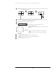
E V E R F O C U S E L E C T R O N I C S C O R P O R A T I O N Front Panel Keypads 17 1 18 2 3 4 5 6 7 19 8 22 20 9 10 11 12 13 14 15 16 21 Keys: 1 5 6 7 CH1 ~CH4: Press channel key (1~4) to display the video image in full screen format for the channel specified. MODE: Press to switch between Picture-In-Picture and Quad modes. ~ 4 ZOOM: Pressing this key while viewing a full screen image will display a magnified resolution of the image on the monitor.
E V E R F O C U S 16 E L E C T R O N I C S C O R P O R A T I O N Display: Pressing this key once will turn the display on. Pressing it a second time will give you Hard Disk Drive statistics. CH1 CH2 CH1 2003/04/22 10:41:00 Disk:120 GB(0) CH3 Display OFF 17 18 19 CH2 2003/04/22 10:42:00 CH4 CH3 LIVE: 60IPS DISK:80G CH4 Display Date/Time and Titles HDD KEY: Turning this key to the lock position will activate the Hard Drive for recording and keep it securely locked into the DVR.
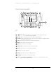
E V E R F O C U S E L E C T R O N I C S C O R P O R A T I O N Back Panel Connections 10 3 8 1 6 5 2 7 4 9 POWER 1 Main Power plug: Connect the DC12~24V power source to Adapter for AC100~240V. AUDIO 2 Audio IN: Audio input for recording. Audio OUT: Audio output can be set to “ON” or “OFF” in Setup Menu.
E V E R F O C U S E L E C T R O N I C S C O R P O R A T I O N MONITOR 3 4 MAIN MONITOR: This connector is used for the Main monitor display, a number of different display modes may be selected for viewing. This output must be used to display the menu settings. CALL MONITOR: This connector is used for the Call (secondary) monitor. This monitor can only display full screen pictures.
E V E R F O C U S E L E C T R O N I C S C O R P O R A T I O N RS232 8 RS232 connector: Connect D-Sub 9 pin connector to RS232 port for remote control. RS485 9 RS485 connector: RJ 45 Connector to Cascade multi Digital Video Recorder. 10 FAN: Cooling FAN.
E V E R F O C U S E L E C T R O N I C S C O R P O R A T I O N Chapter 2 Installation The installations described below should be made by qualified service personnel or system installers. Please refer to the following diagram for the basic wiring connections. ¾ Please note: Monitors and Cameras must be purchased separately.
E V E R F O C U S E L E C T R O N I C S C O R P O R A T I O N Basic Wiring Instructions Please refer to diagram 1 on page 9 to assist you with this portion of the installation. ¾ Power: Connect the power source or adapter into the power socket shown in diagram 1. Please note: Do not plug the digital video recorder into the same power source as the cameras. ¾ Cameras: Connect each cameras video output to the video input on the digital video recorder shown in diagram 1.
E V E R F O C U S E L E C T R O N I C S C O R P O R A T I O N Hard Disk Drive Installation The first step in installing the hard drive is to insert the hard drive sleeve into the machine. The hard disk drive default setting is initially set to master. The second step is to insert the key provided and turn the tray key to the lock position. If this process is ignored the hard disk drive will not be detected.
E V E R F O C U S E L E C T R O N I C S C O R P O R A T I O N Chapter 3 DVR Menu Setup Assuming you have completed the first two chapters of this manual. You are now ready to begin setting up the digital video recorder menu. To begin this process press the MENU key. Once inside the main menu you will find there are 13 setup option pages as follows. 1. CLOCK/LANGUAGE SETTING MENU 2. TITLE SETTING MENU 3. DAYLIGHT SAVING SETTING MENU 4. TIMER SETTING MENU 5. NORMAL RECORD SETTING MENU 6.
E V E R F O C U S E L E C T R O N I C S C O R P O R A T I O N Clock/Language Setting Menu Diagram 2 Diagram two is a screen shot of the Clock/Language Setting Menu. In the Clock/Language Setting Menu the following fields are defined as follows: ¾ Date: This field represents the current date on the DVR. To change this, simply use the arrow keys on the DVR which also represent the channel 14 keys (These are the top four buttons). Use the up and down arrow keys to make your selection.
E V E R F O C U S E L E C T R O N I C S C O R P O R A T I O N ¾ Menu Language: This field is set to English from factory and can not be changed. ¾ Video System: This field is set to NTSC from factory which is the North American Video Standard and can not be changed. The European and Asian Video Standards are PAL. ¾ Version: This field represents the firmware version the digital video recorder is using. Please note: New firmware versions are available for download from our ftp site.
E V E R F O C U S E L E C T R O N I C S C O R P O R A T I O N Title Setting Menu Diagram 3 Diagram three is a screen shot of the Title Setting Menu. In this menu you can set a unique title for each of your cameras. To change this, simply use the arrow keys on the DVR which also represent the channel 1-4 keys (These are the top four buttons). Use the up and down arrow keys to make your selection.
E V E R F O C U S E L E C T R O N I C S C O R P O R A T I O N Daylight Setting Menu Diagram 4 Diagram four is a screen shot of the Daylight Saving Setting Menu. In this menu you can set the DVR to adjust the daylight savings time automatically for you. ¾ Daylight saving: This field is to turn the daylight savings function on or off. To change this, simply use the arrow keys on the DVR which also represent the channel 1-4 keys (These are the top four buttons).
E V E R F O C U S E L E C T R O N I C S C O R P O R A T I O N The third field is set to “March”. This signifies the month in which the daylight savings time will occur. Your options are: Jan through Dec. Use the up and down arrow keys to make your selection. The last two fields represent the time. Use the up and down arrow keys to choose the time you want to go from to the time you want it to be. ¾ Stop Time: This field represents when the daylight savings time will come to an end.
E V E R F O C U S E L E C T R O N I C S C O R P O R A T I O N Timer Setting Menu Diagram 5 Diagram five is a screen shot of the Timer Setting Menu. In this menu you can set a unique timer any day of the week to start recording from a specified start time to an end time. In the Timer Setting Menu the following fields are defined as: ¾ Week: This field represents the day of the week you wish to set the timer record for. Initially it is set to Sun as default. You may choose from MonSun as well as DLY.
E V E R F O C U S E L E C T R O N I C S C O R P O R A T I O N ¾ Speed: This field is used to set the speed at which you would like the timer record to be recording at. To change this, simply use the arrow keys on the DVR which also represent the channel 1-4 keys (These are the top four buttons). Use the up and down arrow keys to make your selection. Please Note: See Appendix B to find the appropriate speed to fit your recording needs.
E V E R F O C U S E L E C T R O N I C S C O R P O R A T I O N Normal Record Setting Menu Diagram 6 Diagram six is a screen shot of the Normal Record Setting Menu. This menu contains the speed and quality for recording all the time. In the Normal Record Setting Menu the following fields are defined as: ¾ Speed: This field represents the speed at which the recorder will be recording all the time.
E V E R F O C U S E L E C T R O N I C S High Superior : : C O R P O R A T I O N 31KB 35KB To change this, simply use the arrow keys on the DVR which also represent the channel 1-4 keys (These are the top four buttons). Use the up and down arrow keys to make your selection. ¾ Disk Full: This field represents what to do when the Hard Disk Drive gets full. In this case the default is set to Rewrite. The other option if you wish to do so is to set the disk full option to Stop.
E V E R F O C U S E L E C T R O N I C S C O R P O R A T I O N Alarm Record Setting Menu Diagram 7 Diagram seven is a screen shot of the Alarm Record Setting Menu. This menu contains all the alarm operations and options needed to successfully complete an alarm recording. In the Alarm Record Setting Menu the following fields are defined as: ¾ Alarm Operations: This field is to turn alarm recording on or off. The Default from the factory is set to on.
E V E R F O C U S E L E C T R O N I C S C O R P O R A T I O N There are six quality levels for recording: Lower Low Basic Standard High Superior : : : : : : 15KB 19KB 23KB 27KB 31KB 35KB To change this, simply use the arrow keys on the DVR which also represent the channel 1-4 keys (These are the top four buttons). Use the up and down arrow keys to make your selection. ¾ Alarm 1-4 Types: These fields represent what to do when a signal is received from the alarm board connector.
E V E R F O C U S E L E C T R O N I C S C O R P O R A T I O N represent the channel 1-4 keys (These are the top four buttons). Use the up and down arrow keys to make your selection. ¾ Recording Speed: This option is to set the speed of the pre-alarm recording. To change this, simply use the arrow keys on the DVR which also represent the channel 1-4 keys (These are the top four buttons). Use the up and down arrow keys to make your selection. : Press or to move the cursor to the left or right.
E V E R F O C U S E L E C T R O N I C S C O R P O R A T I O N Buzzer Setting Menu Diagram 8 Diagram eight is a screen shot of the Buzzer Setting Menu. This menu is to set the internal buzzer. In the Buzzer Setting Menu the following fields are defined as: ¾ Buzzer: This field is to turn the internal buzzer enable or disable the internal buzzer. The default is set to enable. To change this, simply use the arrow keys on the DVR which also represent the channel 1-4 keys (These are the top four buttons).
E V E R F O C U S E L E C T R O N I C S C O R P O R A T I O N DVR which also represent the channel 1-4 keys (These are the top four buttons). Use the up and down arrow keys to make your selection. ¾ Disk Full: This field is to turn the buzzer on or off when the Hard Disk Drive is full. To change this, simply use the arrow keys on the DVR which also represent the channel 1-4 keys (These are the top four buttons). Use the up and down arrow keys to make your selection.
E V E R F O C U S E L E C T R O N I C S C O R P O R A T I O N Archive Setting Menu Diagram 9 Diagram nine is a screen shot of the Archive Setting Menu. This menu is for setting up the way in which video is archived within the machine. In the Archive Setting Menu the following fields are defined as follows: ¾ Picture Size: This field is to set the picture size for copying an image to a Compact Flash card or through the network.
E V E R F O C U S E L E C T R O N I C S C O R P O R A T I O N (These are the top four buttons). Use the up and down arrow keys to make your selection. ¾ Time Stamp Position: This field is to set the position of the time stamp. You can set the time position either on top or bottom. The default is set to top. To change this, simply use the arrow keys on the DVR which also represent the channel 1-4 keys (These are the top four buttons). Use the up and down arrow keys to make your selection.
E V E R F O C U S E L E C T R O N I C S C O R P O R A T I O N Network Setting Menu Diagram 10 Diagram ten is a screen shot of the Network Setting Menu. This menu is for setting up the configuration for networking to the DVR. Please refer to the Networking Chapter of this manual to fully understand how to setup your network for this DVR. In the Network Setting Menu the following fields are defined as follows: ¾ IP Address: This field is to set a static IP Address for the DVR.
E V E R F O C U S E L E C T R O N I C S C O R P O R A T I O N ¾ Net mask: This field is to set the subnet mask for your network so as the DVR will be recognized within the network. Example: 255.255.255.000 To change this, simply use the arrow keys on the DVR which also represent the channel 1-4 keys (These are the top four buttons). Use the up and down arrow keys to make your selection. ¾ Gateway: This field is to set the gateway for your network so the DVR will be recognized within the network.
E V E R F O C U S E L E C T R O N I C S C O R P O R A T I O N Sequence Setting Menu Diagram 11 Diagram eleven is a screen shot of the Sequence Setting Menu. This menu is for setting up the way in which video is sequenced through the main monitor and call monitor outputs. In the Sequence Setting Menu the following fields are defined as follows: ¾ Main Monitor: This field is to set the sequence for the main monitor output.
E V E R F O C U S E L E C T R O N I C S C O R P O R A T I O N ¾ Call Monitor: This field is to set the sequence for the call monitor output. Dwell Time: This field represents the rate at which the cameras will sequence on the call monitor. The dwell time for the auto sequence can be set from 0 to 99 seconds. To change this, simply use the arrow keys on the DVR which also represent the channel 1-4 keys (These are the top four buttons). Use the up and down arrow keys to make your selection.
E V E R F O C U S E L E C T R O N I C S C O R P O R A T I O N RS232/RS485 Setting Menu Diagram 12 Diagram twelve is a screen shot of the RS232/RS485 Setting Menu. This menu is for setting up a connection from the digital recorder to a computer to transfer instructions or information using the HyperTerminal program in Windows.
E V E R F O C U S E L E C T R O N I C S C O R P O R A T I O N ¾ RS232 Parity: This field is to select the parity level at which you will be connected. You can choose between None, Odd, or Even parity levels. Default is set to None. To change this, simply use the arrow keys on the DVR which also represent the channel 1-4 keys (These are the top four buttons). Use the up and down arrow keys to make your selection. ¾ RS232 Data Bit: This field is the data bit at which you will be transferring.
E V E R F O C U S E L E C T R O N I C S C O R P O R A T I O N ¾ RS232/RS485 ID: This entry is used to assign each device its own ID code if more than one unit is used through the RS232/RS485 connection. There are two ID codes for the DVR: 001 or 002. The default is set to 001. To change this, simply use the arrow keys on the DVR which also represent the channel 1-4 keys (These are the top four buttons). Use the up and down arrow keys to make your selection.
E V E R F O C U S E L E C T R O N I C S C O R P O R A T I O N Motion Record Setting Menu Diagram 13 Diagram thirteen is a screen shot of the Motion Record Setting Menu. This menu is for setting up the digital recorder for motion recording. In the Motion Record Setting Menu the following fields are defined as follows: ¾ Recording Speed: This field represents the speed at which the recorder will be recording when motion is detected.
E V E R F O C U S E L E C T R O N I C S Standard High Superior : : : C O R P O R A T I O N 27KB 31KB 35KB To change this, simply use the arrow keys on the DVR which also represent the channel 1-4 keys (These are the top four buttons). Use the up and down arrow keys to make your selection. ¾ CH: This field represents the camera channels 1 through 4. ¾ OP: This field is to set the option of turning motion on or off. If OP is turned on the DVR will respond by recording when motion occurs.
E V E R F O C U S E L E C T R O N I C S C O R P O R A T I O N ¾ Diagram 14 shows a screen shot of the manually edit screen. Use the arrow buttons to move through the squares. Initially all the squares are pink in color signifying that these squares are set up to pick up motion. To deselect a square simply move over the square and press the ENTER button. Diagram 15 shows another screen shot of a manually edited screen after editing has been accomplished.
E V E R F O C U S E L E C T R O N I C S C O R P O R A T I O N System Setting Menu Diagram 16 Diagram sixteen is a screen shot of the System Setting Menu. This menu is for setting up any additional options and restoring defaults to the digital recorder. In the System Setting Menu the following fields are defined as follows: ¾ Play with Audio: This field is to turn on audio while playing video which contains prerecorded audio. This option can be turned on or off. The default is set to on.
E V E R F O C U S E L E C T R O N I C S C O R P O R A T I O N you if you want to do a system update again. Use the arrow buttons to select yes and press the enter button. Please Note: See System Update Chapter for more details and diagrams. Also after the system has updated successfully, be sure to cycle the power to the digital recorder by turning the power off and then back on. ¾ Load Default: This entry is to set the DVR back to factory settings.
E V E R F O C U S E L E C T R O N I C S C O R P O R A T I O N Chapter 4 Recording Overview Before continuing please be sure to have reviewed DVR Menu Setup (Chapter 3). You are now ready to begin setting up the machine for normal recording. This chapter will show you how to setup the recorder for basic recording. Basic Recording Setup ¾ Assuming you have completed the setup options in Chapter 1 and 2. Log into the DVR menu by pressing the Menu button.
E V E R F O C U S E L E C T R O N I C S C O R P O R A T I O N ¾ To stop recording simply press the Stop button. Please Note: When the Hard Drive is full, the DVR will either stop recording automatically or overwrite from the beginning of the hard drive. This is all dependent on what was set in the normal record setting (see page 19). Timer Recording Setup ¾ Assuming you have completed the setup options in Chapter 1 and 2. Log into the DVR menu by pressing the Menu button.
E V E R F O C U S E L E C T R O N I C S C O R P O R A T I O N Please Note: When the Hard Drive is full, the DVR will either stop recording automatically or overwrite from the beginning of the hard drive. This is all dependent on what was set in the normal record setting (see page 19). Motion Recording Setup ¾ Assuming you have completed the setup options in Chapter 1 and 2. Log into the DVR menu by pressing the Menu button.
E V E R F O C U S E L E C T R O N I C S C O R P O R A T I O N Diagram 20 ¾ To stop recording simply press the Stop button. Please Note: When the Hard Drive is full, the DVR will either stop recording automatically or overwrite from the beginning of the hard drive. This is all dependent on what was set in the normal record setting (see page 19). Alarm Recording Setup ¾ Assuming you have completed the setup options in Chapter 1 and 2. Log into the DVR menu by pressing the Menu button.
E V E R F O C U S E L E C T R O N I C S C O R P O R A T I O N Diagram 21 ¾ To stop recording simply press the Stop button. Please Note: When the Hard Drive is full, the DVR will either stop recording automatically or overwrite from the beginning of the hard drive. This is all dependent on what was set in the normal record setting (see page 19).
E V E R F O C U S E L E C T R O N I C S C O R P O R A T I O N Chapter 5 Playback Overview Before continuing please be sure to have reviewed DVR Menu Setup (Chapter 3). You are now ready to begin setting up the machine for playback. This chapter will show you how to setup the recorder for basic playback. Basic Playback ¾ Assuming you have completed the setup options in Chapter 1 through 4. If you are in Record mode hit the stop button to stop recording.
E V E R F O C U S E L E C T R O N I C S C O R P O R A T I O N Search Playback 1. Segment List Playback ¾ Assuming you have completed the setup options in Chapter 1 through 4. If you are in Record mode hit the stop button to stop recording. ¾ If the menu pops up when you press the stop button. This usually means you have either the DVR is in Timer record or Motion record. Log into the DVR menu by pressing the Menu button. Go to Either Timer Setting Menu or Motion Record Setting menu and turn them off.
E V E R F O C U S E L E C T R O N I C S C O R P O R A T I O N Diagram 23 ¾ To stop playing back press the stop key. 2. Alarm List Playback ¾ Assuming you have completed the setup options in Chapter 1 through 4. If you are in Record mode hit the stop button to stop recording. ¾ If the menu pops up when you press the stop button. This usually means you have either the DVR is in Timer record or Motion record. Log into the DVR menu by pressing the Menu button.
E V E R F O C U S E L E C T R O N I C S C O R P O R A T I O N ¾ Use the up and down arrow keys to select alarm list and press the enter key. Please Note: If the alarm list is empty it is because there are no alarms or motion being recorded. ¾ Diagram 25 illustrates what the alarm list may look like. Use the up and down arrow keys to choose a segment you want to playback and press the enter key. This in turn will start playing the segment you chose.
E V E R F O C U S E L E C T R O N I C S C O R P O R A T I O N Diagram 26 ¾ Use the up and down arrow keys to select Date/Time and press the enter key. ¾ Diagram 27 illustrates what the Date/Time field may look like. Use the up and down arrow keys to enter a date and time you want to playback, highlight search, and press the enter key. This in turn will start playing the segment you chose. Diagram 27 ¾ To stop playing back press the stop key.
E V E R F O C U S E L E C T R O N I C S C O R P O R A T I O N Chapter 6 Copying Video Before continuing please be sure to have reviewed the preceding chapters. You are now ready to copy an image or video from the DVR. This chapter will show you how to copy a still image or movie from the recorder. ¾ Please Note: Lexar Compact Flash Cards are not compatible with our digital recorders. We suggest using Sandisk or Kingston Compact Flash Cards.
E V E R F O C U S E L E C T R O N I C S C O R P O R A T I O N ¾ You will then see “Copying …” on the screen while it is copying to the flash card. When it has finished copying will disappear from the screen. Diagram 28 Diagram 29 ¾ The image on the Compact flash card will be stored as a jpeg file. Copy as a MOV File ¾ First step is to play the video you want to archive. Please refer to chapter 5 to for playing back video.
E V E R F O C U S E L E C T R O N I C S C O R P O R A T I O N ¾ To exit press the stop button. ¾ The video is now stored on the Compact flash card as a MOV file. This type of file can be played using QuickTime video player. You can download this program for free from www.quicktime.com. Other Archiving Methods ¾ Other methods of archiving may include Powercon software which can be found on our ftp site ( ftp://64.210.7.210 ).
E V E R F O C U S E L E C T R O N I C S C O R P O R A T I O N Chapter 7 Audio Overview This chapter will try to give you details on how to setup audio on the DVR. Before we begin the process of connecting audio to your digital recorder we should have the following items. A Line level microphone (RCA input) and speakers for playback output (RCA). You will not be able to hear audio live unless an audio processor is looped through or placed between the mic and the DVR.
E V E R F O C U S E L E C T R O N I C S C O R P O R A T I O N Chapter 8 How to Upgrade Firmware on the DVR? This chapter will try to give you a detailed instruction on how to upgrade the DVR. This will be a helpful in completing the upgrading process. ¾ Please go to ftp://64.210.7.210 and go to DVR Firmware upgrade folder. Then click on the folder that represents you’re the model number of your DVR. ¾ Copy the .HEX to CF card using the Compact Flash reader that came with your DVR (from a computer).
E V E R F O C U S E L E C T R O N I C S C O R P O R A T I O N ¾ Highlight YES again and press enter (use jog wheel to select). ¾ Next to System Upgrade you will notice it say "Reading....then Programming...then Success..." ¾ Once you have read success log out of the menu by pressing the menu button twice. Then turn the power on the DVR off and turn it back on. .
E V E R F O C U S E L E C T R O N I C S C O R P O R A T I O N Chapter 9 Networking Overview This chapter will try to give you a detailed instruction on how to network the DVR. Before we begin the process of networking your digital recorder we should have a working knowledge of what a network is and how it works. This will be a helpful in completing the networking process.
E V E R F O C U S E L E C T R O N I C S C O R P O R A T I O N Gateway Address Each host in a LAN has a gateway. A gateway address is composed of four octets (numbers in the range of 0 to 255) separated by decimal points. The gateway address is used to uniquely identify a host or computer on the LAN which assigns the IP addresses to your network. For example, a Linksys router has an IP address of 192.168.1.1.
E V E R F O C U S E L E C T R O N I C S C O R P O R A T I O N Pre-Installation Before we begin with the installation we must ask ourselves a few questions in order to figure out where to begin with networking our DVR’s. Do you have Hi-speed Internet? ______________ There are many types of high speed Internet available. Three commonly used ones are T1, Cable, and DSL (in order of speed). Please Note: We suggest having a minimum upload speed of 256KBps.
E V E R F O C U S E L E C T R O N I C S C O R P O R A T I O N DDNS. DDNS is a Dynamic Domain Name Server, a service that provides a central (public) database where DNS information can be stored and retrieved. It allows those using a dynamic IP address to be registered centrally so users can connect to it by name. What type of DVR are you installing? ______________ What Type of Network Connection do you have? Our DVR’s can operate using three distinct types of networking connections. 1.
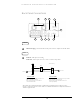
E V E R F O C U S E L E C T R O N I C S C O R P O R A T I O N Simple One to One Connection Cat 5 Cross-over-cable Crossover Ethernet Cable Pin outs: The Diagram below shows the pin configurations for a cross over cable. Diagram 31 Connection Procedure: ¾ The First step is to purchase or make a cross over cable. We recommend purchasing one if you have never made a cross over cable.
E V E R F O C U S E L E C T R O N I C S C O R P O R A T I O N ¾ Assign an IP address of 192.168.001.003 to the DVR, a Subnet mask of 255.255.255.000, and a default gateway of 192.168.001.001. ¾ The next step is to get the computer onto the same network to do this you will need administrator access to your windows machine. ¾ To assign a static IP address in windows 2000/XP.
E V E R F O C U S E L E C T R O N I C S C O R P O R A T I O N 62
E V E R F O C U S E L E C T R O N I C S C O R P O R A T I O N 63
E V E R F O C U S E L E C T R O N I C S C O R P O R A T I O N 64
E V E R F O C U S E L E C T R O N I C S C O R P O R A T I O N ¾ Once you have reached this point click ok and restart both the computer and the digital recorder. ¾ To access the DVR from the computer simply open Internet Explorer and in the address bar type: http://192.168.1.
E V E R F O C U S E L E C T R O N I C S C O R P O R A T I O N Direct High Speed Modem Connection Hi-speed modem Internet Cat 5 Straight Through Cable DVR Straight Through Ethernet Cable Pin outs: The Diagram below shows the pin configurations for a straight cable. Diagram 32 Connection Procedure: ¾ The First step is to purchase or make a straight through cable. We recommend purchasing one if you have never made a straight through cable.
E V E R F O C U S E L E C T R O N I C S C O R P O R A T I O N ¾ Now Log into the DVR menu and using the jog dial from the previous chapter go to the Network Setting Menu. (See page 28 for more instructions) ¾ Assign the Static IP address which you obtained from the internet service provider to the DVR, the Subnet mask from the internet service provider to the DVR, and the default gateway of the internet service provider.
E V E R F O C U S E L E C T R O N I C S C O R P O R A T I O N Router or LAN Connection Hi-speed modem Internet Cat 5 Straight Through Cable DVR Router Straight Through Ethernet Cable Pin outs: The Diagram below shows the pin configurations for a straight cable. Diagram 33 Connection Procedure: ¾ The First step is to purchase or make a straight through cable. We recommend purchasing one if you have never made a straight through cable.
E V E R F O C U S E L E C T R O N I C S C O R P O R A T I O N ¾ Once you have a straight through cable plug one end into the LAN port on the back of the recorder and the other into the router. ¾ Now Log into the DVR menu and using the jog dial from the previous chapter go to the Network Setting Menu. (See page 28 for more instructions) ¾ If you have a Linksys Router: Assign an IP address of 192.168.001.050 to the DVR, a Subnet mask of 255.255.255.000, and a default gateway of 192.168.001.001.
E V E R F O C U S ¾ E L E C T R O N I C S C O R P O R A T I O N Please Note: Make sure the modem is in bridge mode. If your Internet Service Provider is BellSouth you will have a modem/router. BellSouth provides a Westell modem that includes a built-in router. You will need to disable the router functionality. ¾ The next step is to open ports within your router.
E V E R F O C U S E L E C T R O N I C S C O R P O R A T I O N Chapter 10 Linksys Port Forwarding This chapter will cover a few simple configurations for the Linksys router. Please understand we do not support this product and will not give tech support on it. If you need Technical support on this router you must call Linksys. This Chapter is to offer some help to the installer and end user nothing more.
E V E R F O C U S E L E C T R O N I C S C O R P O R A T I O N The first screen that appears displays the Setup tab. This allows you to change the Router's general settings. Change these settings as described here and click the Save Settings button to apply your changes or Cancel Changes to cancel your changes. The Applications and Gaming Tab allows you to set up public services on your network, such as web servers, ftp servers, e-mail servers, or other specialized Internet applications.
E V E R F O C U S E L E C T R O N I C S C O R P O R A T I O N Application - In this field, enter the name you wish to give the application. Each name can be up to 12 characters. Start/End - This is the port range. Enter the number that starts the port range under Start and the number that ends the range under End. Protocol - Enter the protocol used for this application, either TCP or UDP, or Both. IP Address - For each application, enter the IP Address of the PC running the specific application.
E V E R F O C U S DVR DVR DVR DVR E L E C T R O N I C S 3333 to 3333 4444 to 4444 6666 to 6666 1600 to 1600 C O R P O R A T I O N Both Both Both Both 192.168.1.50 192.168.1.50 192.168.1.50 192.168.1.50 Enable Enable Enable Enable ¾ The next step is to open ports within your router. Open virtual ports in the router. o EDR Ports to open: 80, 1111, 1600 o EDSR Ports to open: 80, 1111, 2222, 3333, 4444, 6666 ¾ If your Internet Service Provider Blocks port 80.
E V E R F O C U S E L E C T R O N I C S C O R P O R A T I O N 1. Enter the name of the application in the appropriate Application Name field. 2. Next to the name of the application, enter the number of the external port used by the server in the Ext. Port column. Check with the Internet application software documentation for more information. 3. On the same line, select the protocol UDP or TCP. 4. Enter the number of the internal port used by the server in the Int. Port column.
E V E R F O C U S E L E C T R O N I C S C O R P O R A T I O N DDNS Service - From this pull-down menu, enter the DDNS service with which you have membership. User Name - Enter the User Name for your DDNS account. Password - Enter the Password for your DDNS account. Host Name - The is the DDNS URL assigned by the DDNS service. Internet IP Address - This is the Router’s current IP Address as seen on the Internet. Status - This displays the status of the DDNS connection.
E V E R F O C U S E L E C T R O N I C S C O R P O R A T I O N Chapter 11 D-Link Port Forwarding This chapter will cover a few simple configurations for the D-Link router. Please understand we do not support this product and will not give tech support on it. If you need Technical support on this router you must call D-Link. This Chapter is to offer some help to the installer and end user nothing more.
E V E R F O C U S E L E C T R O N I C S C O R P O R A T I O N ¾ The next step is to open ports within your router. Go to Virtual Server in the router. Example1: Protocol Type - The protocol used for the virtual service. Public Port - The port number on the WAN (Wide Area Network) side that will be used to access the virtual service. Private Port - The port number of the service used by the Private IP computer. Schedule - The schedule of time when the virtual service will be enabled.
E V E R F O C U S E L E C T R O N I C S C O R P O R A T I O N Name - Enter the name referencing the virtual service Private IP - The server computer in the LAN (Local Area Network) that will be providing the virtual services. If you have a Web server that you wanted Internet users to access at all times, you would need to enable it. Web (HTTP) server is on LAN (Local Area Network) computer 192.168.0.50 HTTP uses port 80, TCP and UDP. Name: DVR Private IP: 192.168.0.
E V E R F O C U S E L E C T R O N I C S C O R P O R A T I O N Dynamic DNS Dynamic Domain Name System is a method of keeping a domain name linked to a changing IP Address. This is a useful feature since many computers do not use a static IP address. ¾ To setup Dynamic DNS simple go to Tools and the Misc. At the bottom of the screen you will be able to enable DynDNS. ¾ Once you have enabled it enter the server address of DynDNS.org: members.dyndns.org ¾ Then enter the hostname you created with DynDNS.
E V E R F O C U S E L E C T R O N I C S C O R P O R A T I O N 81
E V E R F O C U S E L E C T R O N I C S C O R P O R A T I O N Chapter 12 DDNS This chapter will cover a few simple configurations for setting up DDNS. Please understand we do not support this product and will not give tech support on it. If you need Technical support on DDNS you must call Linksys or D-Link. This Chapter is to offer some help to the installer and end user nothing more. Creating a DDNS Account ¾ The first step is to open Internet Explorer and in the address bar type: http://www.dyndns.
E V E R F O C U S E L E C T R O N I C S C O R P O R A T I O N ¾ This is where you file out the information DynDNS requires. You will then receive an email to confirm your account once you confirm you will login into DynDNS.org. ¾ After you have logged in click on click on the account tab and the click on Add Host link right next to Dynamic DNS. ¾ The next step is to add a host name with an extension. ¾ The IP address should already be entered for you.
E V E R F O C U S E L E C T R O N I C S C O R P O R A T I O N ¾ To access the DVR from a computer simply open Internet Explorer and in the address bar type: http:// The DDNS you created example everfocu.homeip.
E V E R F O C U S E L E C T R O N I C S C O R P O R A T I O N Chapter 13 Viewing through Internet Explorer ¾ To access the DVR from a computer simply open Internet Explorer and in the address bar type: http:// (LAN or IP address of your internet service provider) ¾ The digital video login page will appear on the screen similar to the one shown above. ¾ User must enter a user name and password to access the recorder. You can find your user name and password in the Network setting menu of your DVR.
E V E R F O C U S E L E C T R O N I C S C O R P O R A T I O N ¾ Then click on the submit button and you will be logged into your recorder.
E V E R F O C U S E L E C T R O N I C S C O R P O R A T I O N 87
E V E R F O C U S E L E C T R O N I C S C O R P O R A T I O N ¾ Please Note: If any icon is grayed, it means that particular function is not accessible.
E V E R F O C U S E L E C T R O N I C S C O R P O R A T I O N Chapter 14 Interface Specifications This Digital Video Recorder may be controlled by a computer or a terminal via the standard D-SUB 9-pin RS-232 connector.
E V E R F O C U S E L E C T R O N I C S C O R P O R A T I O N Transmission Setting There are 6 different speeds that can be used to transmit instruction or information through the RS232/RS485 port on the device, 1200 baud, 2400 baud, 4800 baud, 9600 baud, 19200 baud, and 3840 baud. The default setting from the factory is 9600 baud. Please refer to RS232/RS485 Setting Menu on page 32 for details. Remote Control Protocol A computer can be used to control the DVR by sending the packet as follows.
91
92
Appendix A Remote Control 93
Appendix B Time Lapse Mode Recording Time 94
95
Appendix C Alarm Board Configuration 96
97
98
Troubleshooting If you have difficulty operating your system, run through the following checklist to see if you can solve the problem. The DVR will not go into record mode? Make sure the HDD is locked in with the keys. Also check to make sure the hard drives are set to Master. A diagram located on the Hard Drive Label will show you how to set the drive to master. DVR only records for a few hours? If motion recording is not properly set up this problem will arise.
The DVR displays no picture? First question you should ask yourself is the equipment wired properly. Please see your installation manual for help. The second question to ask yourself0, do all the wires used work properly. The next step is to verify the recorder is getting the correct amount of power. There is no display coming from one of the channels on the DVR? The first step is to verify is the problem coming from the recorder or the camera.
www.tzo.com. (Preferred routers: Linksys BEFSR41 V3 or DLINK DI624 or any router that offers DDNS.