IWAVEPORT WLM54GP30-ESD USER MANUAL
© Copyright 2007 Compex Systems Pte Ltd All Rights Reserved This docume nt contains information, which is protected by copyright. Reproduction, adaptation or tra nslation without p rior pe rmission is p rohibited, except as allowed under the copyright laws. Trademark Information Compex® is a regi stered t rademarks o f Co mpex, I nc. Mic rosoft Windows an d the W indows l ogo are th e tr ademarks of Microsoft Corp. NetWare is th e registered tr ademark of N ovell I nc.
FCC NOTICE This device h as bee n tested a nd found to comply with the limits fo r a C lass B digital device, pursuant to Part 15 of the FCC Ru les. These limits are designed to provide re asonable protection ag ainst harmful interfe rence in a re sidential installation. Thi s devi ce g enerates, uses and c an r adiate r adio fr equency energy and, if no t installed and used in accordance with the instructions, may cause h armful inter ference to ra dio c ommunications.
End Product Labeling The fi nal en d p roduct must be labeled i n a visible ar ea w ith the following: “Contains FCC ID: TK4-WLM54GP30ESD” ICES 003 Statement This Class B digital apparatus complies with Canadian ICES-003. Declaration of Conformity Compex, Inc. declares the following: Product Name: Compex Wireless Mini-PCI Network Adapter Model N o.
Technical Support Centers Contact the technical support center that services your location. U.S.A., Canada, Latin America and South America Write Call Fax Compex, Inc. 840 Columbia Street, Suite B, Brea, CA92821, USA Tel: +1 (714) 482-0333 (8 a.m.-5 p.m. Pacific time) Tel: +1 (800) 279-8891 (Ext.
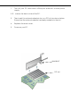
1. 2. R Turn off your PC and switch off the pow er from th e m ain pow er supply. emove the back cover of the PC. 3. Then i nsert th e n etwork ad apter i nto you r P CI s lot as s hown be low. Ensure that the network adapter is properly seated into the slot. 4. Replace the back cover. 5. Power on your PC.
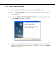
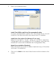
1.2 D river & Utility Installation 1. Insert the Product CD into your computer CD-ROM drive. 2. Click on Driver & Utility section and the sy stem will run the setup.exe automatically. 3. N ext, the Atheros Client Installation Program screen appea rs. Cl ick on the Next> button to proceed. 4. When th e License Agr eement s creen appears, you are r equired to read an d accept th e agreement to c ontinue. Clic k o n th e Next> button to proceed.
5. Select your preferred setup: Install Client Utilities and Driver (Recommended) option You a re r ecommended to sel ect this setup ty pe. This op tion wi ll install both the driver and utility that support your PCI adapter. Install Driver Only option (For Windows XP user only) Select th is op tion if y ou are going to u se the W ireless Zero Configuration U tility to configure yo ur PCI a dapter. Note t hat only Windows XP comes with the Wireless Zero Configuration Utility.
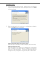
For Windows XP users 7. If y ou a re us ing W indows XP as op erating sy stem, t he f ollowing screen will appear. Read the notice carefully and click on the Next> button to proceed. 8. Select your ch oice of tool to assist you i n configuring your adapter. Click on the Next> button to proceed. Atheros Client Utility (ACU) and Supplicant option Select this option to install your network adapter.
If y ou ha ve se lected Third Party Supplicant configuration tool, a screen similar to tha t be low will ap pear, p rompting y ou to enable/disable the system tray icon. 9. Click on th e c heckbox bes ides Enable Atheros System Tray Utility and cl ick on the Next> b utton to proceed. 10. The s creen below appears to i nform y ou th at th e driver w ill b e automatically install ed if you have already inse rted y our cl ient adapter into the PCI slot of your computer.
. Click on the OK button to reboot your system and this w ill complete the installation. Chapter 2 Using the System Tray Utility This ch apter w ill elaborate on the Atheros sy stem tray u tility found at th e rig ht b ottom co rner of you r screen. Right click on the utility icon and the menu will appear.
Help Open the online help. Exit Exit the Atheros Client Utility application. Once you exit, the icon will disa ppear from the system tray. Open Atheros Client Utility… Launch the Client Utility.
Reauthenticate Reauthenticate to a L EAP-configured a ccess point each tim e you l ogin to a LEAP network. Select Profile Click on a co nfiguration profile name to switch to a particular wireless network. If no configuration profile exists, you will need to add a profile first. Connection Status To view the connection status of your wireless PCI adapter. Alternatively, you may also double click on the utility icon in the system tray. Active Profile Displays the name of the active configuration profile.
Link Quality States the quality of the link connection. SSID Displays the SSID of the network to which the network adapter is associated. Access Point Name Shows the name of the access point the wireless adapter is connected to (if any). Access Point IP Address Shows the IP address of the access point the wireless adapter is connected to (if any). Current Receive Rate Displays the data rate at which the wireless adapter is currently receiving from the wireless network.
Chapter 3 Utility Features This chapter shows you how to make u se of th e utility to view the status of your wireless c onnection, to change y our set tings an d al so to monitor y our wireless performance via the network statistics. 3.1 Current Status Tab Displays the performance of the network adapter in the wireless network. Wireless-AG Current Status Upon cl icking on the Advanced b utton, y ou wil l b e able to vie w all information on th e r espective pro file, e. g.
3.2 Prof ile Management Tab Selecting this tab displays the profiles and the details. You onl y need to cr eate a profile if you ha ve mor e tha n one wi reless connection. 3.3 Diagnostics Tab The Diagnostics tab lists the following receive and transmit diagnostics for packets received by or transmitted to the network adapter.
This button shows more deta iled statistical information on frames that are either received by or transmitted by the network adapter. This button allows you to run the diagn ostic test, save the test report and view the test results on the wireless adapter configuration and association.
Chapter 4 Utility Configuration This chapter will elaborate on the Cl ient Manager configuration of th e network adapter using some simple examples. the wireless clients communica te through router, which are devices that act as base station for all wireless communication. Data packets from the wireless clients a re tra nsferred t o the wi reless route r be fore be ing transmitted to other h osts on the netw ork. The number of wireless clients supported depends on the router.
4.1 Co nfiguration Mode In this example, three work station act as wireless clients to communicate with the w ireless router. Once all con figuration ha s been done, wire less clients w ith the sam e SSI D as the AP will be abl e to acc ess wirelessl y to PC1 via the wireless router For Router Ensure that yo u have en abled the DHCP server in your router an d that your wireless clients are set to receive their IP address dynamically so that the wireless router can assign an IP address to them.
For PC 1 1. Activate your utility. 2. Go to the Profile Management tab, click on the Scan button to look for the wireless AP. 3. Click on the Refresh butto n if you r syst em is un able t o de tect yo ur wireless AP . Once found, se lect the Network Name (SSID) used by the router: wireless-router and click on th e Activate button to add i t to your profile list. Notice that the SSID has already been pre-configured in this profile.
The SSI D of both the wireless router and the wirele ss cl ient must b e t he same for them to communicate with one another. 4. E nter the Profile Name, e.g. Workstation 2 for easy identification.
5. Next, proceed to the Security tab . The wire less cl ient must us e t he same se curity m ode as the ro uter. In our example , s elect WPA Passphrase and click on the Configure… button. 6. Enter the enc ryption key in the field provided. Pl ease note that this key must be the sa me as the one that you had configured for your wireless router. 7. Click on the OK button to update the changes.
Alternatively, you can a lso check the con nection from the MS-DOS Prompt. Fr om PC2 , simpl y p roceed to the Start Me nu, Run… and type in cmd. Click on the OK button. In the MS-DOS Prompt window, type ping 192.168.168.1 –t, whereby this IP address belongs to your access point. When the screen appears: Pinging 192.168.168.1: bytes=32 time=2ms TTL=128 Pinging 192.168.168.1: bytes=32 time=2ms TTL=128 Pinging 192.168.168.1: bytes=32 time=2ms TTL=128 …….
Click on New b utton to cr eate a new profil e. Enter the profile name ( a unique name to identify th is p rofile), a cl ient n ame and the SSI D of th e wireless netw ork to conne ct to. Note that the Client name refers t o th e name that is registered to your PC. You can enter up to 3 different SSIDs in order of pref erence, p er profile.
For d etails o n h ow to set the dif ferent authentication and encryption types available u nder the Security Ta b, kindly re fer to Chapter 7 “Types of Authentic ation and Encryption mode” Click on the OK button to update the changes. Notice that ABC has been to the profile list.
To mod ify a n e xisting profile, select the profile that you wish to m odify and click on this button. We are using profile: Any as an example.
To delete an existing profile, select the particular profile that you wish to delete a nd cl ick on this b utton. We are usin g p rofile: default as an example.
To activ ate a profile, selec t the p rofile and c lick on th is button . W e are using profile: wireless-AP as an example. Once a profile is activated, this name: wireless-AP.
This fu nction allows y ou to save th e s ettings of y our p rofile on to disk. Select the profile that y ou wish to sa ve and click on this button. We are using profile: ESSID as an example. Choose th e f older to s ave to, en ter the name u nder w hich to save th e profile and click on the Save button. Now, your profile is saved to your selected folder.
This function allows you to retrieve a saved profile from disk. We are using profile: ESSID as an example. Go to th e folder where you have saved your profile, select ESSID.prf and click on the Open button. Notice that the profile: ESSID has been imported to the list of profiles. If you ha ve crea ted se veral profil es, th is function allow s y ou to establ ish the priority order in which the network adapter should try to connect to a WLAN.
through the 1 st profile, it w ill then try to conn ect using the 2 nd profile and so on. Notice that if this function is disabled, this means tha t you have not a dded any profile in the Auto Selected Profiles list. When auto pr ofile se lection is en abled, the network adapter scans for available wireless networks and will connect to the highest p riority profile that matches the networks detected. To do so, simply click on t he Add button from the Available Profiles list.
Select and click on the Add button to transfer another profile. You need to transfer at least two profiles to the Auto Selected Profiles list to activate the Auto Select Profile function. Transmit Power Level Specifies the wire less tra nsmit p ower to be used. Reducin g the power level lowers the risk of interference with other nearby wireless devices and conserves battery power but decreases radio range.
The P CI ad apter wakes u p more often an d res ponds sooner to network requests in Normal mode than in Maximum mode; and the Maximum mode consumes less power than Normal mode. Network Type Select ei ther Infrastructure if y ou are conn ecting to the W LAN u sing an access point 802.11b Preamble The preamble is part of the IEEE 802.11b physical layer specification. It is mandatory for all 802.11b devices to support the long preamble format, but they may op tionally s upport th e s hort pr eamble.
Appendix 1.Technical Specifications Network Protocol, Standards and Electrical Emissions Industry Standards • • IEEE 802.11g IEEE 802.11b Performance Operating Frequency Modulation • • • • • • • • Antenna Type External 2dBi antenna and an SMA-type connector Network Interface PCI 2.