
Service manual
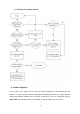


or a whole driver module directly.
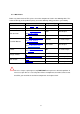
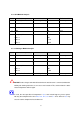
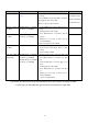
6.3.10 others
In previous sections, we pay attention to the components on PSDR/Charger, in this section,
we are trying to list some possible failure phenomenon not stated before and on control PCB
sub-assembly. They are list as following.
Fail for Phenomenon Possible
components
Comment
Bus over-voltage
1.Bus over-voltage fault alarm and
display occur
2.Bus voltage doesn’t meet spec.
PFC IGBT Driver
module, 2k/3k:Q09,
1k:Q14
Inverter Inverter fault alarm and display
occur.
1.Components listed
in previous section.
2.U8, U9, U10, U11
2. This IC’s are
on CNTL PCB
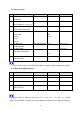
UPS can’t start,
but not the
problem stated
before.
1.LCD’s light, but are active
randomly or abnormally.
2.Buzzer beeps abnormally.
U18 (CPU on CNTL)
Audible problem Buzzer does not beep at start-up or
for alarm.
Q5, BZ1 On CNTL PCB
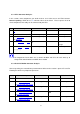
Start-up
1.UPS is bypass after the mains is
on.
2.No response after press ON
button.
1.SPS Module Q201
2.U13
1.on PSDR
2.on CNTL
PCB
O/P DC balance O/P DC balance is out of spec.
1.PFC IGBT Driver
module, Q09 or Q14
(on PSDR)
2.U22 (on CNTL)
1.Bus feedback
loop.
2.Auto-balance
circuit.
For O/P DC balance problem, it is almost caused by incorrect bus voltage. If this indeed
happen, please try to find which mode the problem arise. For example, if it happens under
Line mode, you must measure bus voltages to see if they are correct. After doing this,
39