
Service manual


Ultraview 1030/1050 Monitors — Service Manual
5-21
Troubleshooting
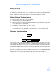
Figure 5-9: Location of D2 on recorder CPU
If a diagnostic error occurs, the recorder will attempt to print a diagnostic line instead of its usual
sign-on message. This line is a series of hex numbers. Non-zero numbers represent error codes.
If the recorder is recognized by the monitor at power-ON, a PRINTER CONTROLS key is present.
Recorder Tips
If an OPEN DOOR key is not on the installed recorder:
1 Unplug the external power supply and rechargeable battery(ies).
2 Remove the recorder assembly by opening the paper door and loosening the two captive
screws.
3 Remove the recorder CPU by loosening the thumb screw, fastening it to the chassis, pulling it
outward, and lifting it out.
4 Re-install the recorder CPU by firmly inserting it into the connector. Occasionally when
installing a Recorder CPU, a second effort proves that the connection was not fully seated.
Tighten the thumb screw.
5 Re-install the recorder assembly and apply power. If the recorder door is closed and paper is
properly loaded, the Recorder CPU initiates a self-test. If the test is successful, a line of
1/4” bars will print on the paper followed by the monitor’s model number, software version, and
software date.
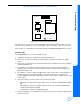
6 If the self-test fails, open the recorder door and remove the paper:
• If the diagnostics detected a software failure on the recorder CPU, LED D2 will be steadily
ON.
• If the diagnostics detected a hardware failure in the recorder assembly, LED D2 will be
continuously flashing ON and OFF.
• If no failures were detected, LED D2 will be OFF.
7 If the recorder and the associated interface circuitry is good, an error report line is printed upon
detection of an error.
D2
front
rear
connector
recorder cpu