
Service manual


Ultraview 1030/1050 Monitors — Service Manual
5-26
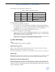
The following errors are indicated by a flashing code:
If the Channel does not sign ON:
1 Check that side panel LED is steadily ON.
• If yes, the processor is not running. Replace EPROM U37 and the CO
2
/SDLC PCBA.
• If no, open the rear cover and remove the I/O and wireless PCBA (if equipped) exposing
the PCBA. Attach the loose end of the SDLC 9-pin connector to another monitor
(90309/90303, etc.). Power ON the unit and proceed to step 2.
2 Check to see if any LEDs are on for the PCBA.
• If they are, check to see if they are blinking approximately once per second (indicating a
watchdog time-out). If there are no communications with the monitor, use another monitor.
Replace EPLD U36 and the CO
2
/SDLC PCBA.
• If they are not, check power to the capnography unit. Check for +5V at J1 pin 2. Check for
+12V at J1 pin 11. If voltage is present, replace the CO
2
/SDLC PCBA.
O
2
Does Not Display
Note:
Model 90369-M does not include O
2
capability.
Nonfunctional O
2
Sensor
Plug one end of a known good O
2
cable into the O
2
sensor connector, measure the voltage
between the tip and sleeve of the cable on the other end.
The sensor should produce 7 to 15 mV in room air. Replace the O
2
sensor if it is less than 7 mV.
Bad O
2
Cable
With a known good O
2
sensor connected to one end, you should measure 7 to 15 mV in room air.
If a signal is measured at the sensor but not at the end of the cable, then replace the cable.
EMI Interface PCBA (for Option H only)
Attach a known good O
2
sensor and cable to the O
2
connector on the front panel of the module.
Connect the DVM to pin 1 and pin 2 of J1 on the EMI interface PCBA. You should measure 7 to
15 mV in room air. If a signal is measured at the external cable but not between pins 1 and 2, then
replace the EMI interface PCBA.
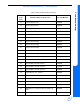
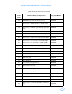
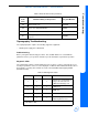
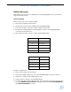
Table 4: Flashing LED Diagnostic Codes
D1 D2 D3 Problem
0 0 1 Timer 0 circuitry
0 1 0 Timer 1 circuitry (SDLC clock)
1 1 1 E2PROM error