
Service manual


Ultraview 1030/1050 Monitors — Service Manual
2-28
Warning:
Ensure that the Ethernet wall plate and the shield of the Ethernet connecting cable are
bonded to the hospital grounding system.
Ethernet Installation
Caution:
Only qualified personnel should attempt to install a monitor to an Ethernet LAN.
Note:
Detailed installation instructions for an Ethernet local area network (LAN) are beyond the
scope of this document.
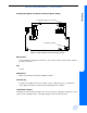
Install the monitor on a suitable table or shelf, ensuring that the air flow to the side air intake vents
is unobstructed, or use a Spacelabs Medical wall mount (P/N 016-0347-xx).
To connect the monitor to the Spacelabs Medical Ethernet LAN:
1 Plug the power cord attached to the monitor’s DC power supply into a standard hospital-grade
AC power source.
2 Turn the monitor power ON.
3 Enter a unique NODE ID, BED NAME, and SUBNET for the monitor. Refer to Software
Configuration on page 2-11 for more information.
Note:
Do not connect the monitor to an Ethernet LAN prior to configuring the network parameters.
The monitor must be properly configured for LAN access before you operate the monitor. If
you fail to correctly configure the monitor, you may interrupt other units also using the LAN.
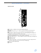
4 Attach the 10Base-T LAN transceiver cable into the phone-type connector on the rear panel of
the monitor.
5 Reconfigure the network to accept the monitor connection to the Ethernet LAN.
Ethernet Removal
1 To remove a monitor from the local area network, disconnect the Ethernet cable from the
Ethernet connection ( ).
Module Tests
To verify that the monitor functions correctly with parameter modules:
1 Insert a 90496 module without the patient cables connected.
• Verify that the vertical ECG screen appears and displays ??? and the message
LEADS OFF.
2 Connect a waveform simulator to the ECG input with a 5-lead patient cable and set the
simulator to a known rate.
• Verify that the ECG count and lead being monitored are displayed to the right of the ECG
parameter key.