
Service manual


Ultraview 1030/1050 Monitors — Service Manual
2-30
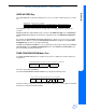
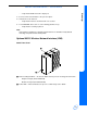
90310 Rear Panel
Ground lug — available for any chassis grounding requirements
Antenna connectors (J1, J3) — screw-on connectors that attach to the pedestal mount
antenna
Ethernet connectors (J2, J4) — connect the 90310 to a Spacelabs Medical network
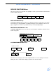
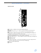
Status LEDs — displays hexadecimal code for errors detected during power up diagnostics.
Displays the channel selection during normal operation
Channel selection thumb wheel — selects the communication channel. Both the 90310 and
Ultraview 1030/1050 must select the same channel to communicate
Captive thumbscrews (4) — secure the PCBA to the 90310 assembly. May be hand-tightened
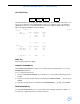
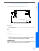
SDLC/power out (J5)
SDLC/power in (P1)
Terminator switch (SW1) — the last daisy-chained 90310 from the power supply must have
this switch enabled (down). All others in this chain are disabled (up)
Model and serial number ID label
FCC label