
Service manual


Ultraview 1030/1050 Monitors — Service Manual
3-6
Video
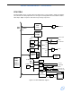
The Ultraview video is implemented using a Chips and Technologies 65554 VGA controller that
resides on the PCI bus. The video system uses 1 MB of EDO DRAM for video memory, and has
analog buffers for the repeater output.
The video controller directly generates digital video signals for the flat panel display. It also
generates equivalent analog RGB signals, which are buffered and sent to the external VGA
connector for connection to a repeater display. Hsync and Vsync signals also go to the VGA
connector.
The 1 MB of DRAM display memory organized as 256 K × 32 - two 256 K × 16 devices. This
provides a wide 32-bit path from the controller to display memory.
Communication between the 7555 and a remote display is possible over a DDC2B channel. This
allows information, such as resolution, to be passed from the remote display to the 65554.
The CPU PCBA also includes a high voltage power inverter to drive the fluorescent backlight tubes
in the display. This circuit is a free running oscillator that generates about 1000 VAC. Although it is
a low power circuit, it can cause an unpleasant minor burn if touched. It is surrounded by warning
markings on the PCBA. The backlight can be turned ON or OFF by the CPU via a signal from the
video controller, and it can be dimmed (run at lower voltage) by the CPU via a signal from one of
the latches on the ISA bus.
The power to the flat panel is routed through a FET, which is switched via a signal from the video
controller. This is so that the controller can properly sequence the activation of the logic signals
relative to power during power ON.
Ethernet
A Digital 21143 PCI based Ethernet controller provides the network interface. It is capable of both
10 and 100 MB Ethernet, however only 10 MB is used at this time. This chip directly attaches to
the PCI bus and uses a transformer/filter and several passive components to attach to 10BaseT
ethernet.
PMC Connector
One set of PCI Mezzanine Card (PMC) connectors are provided on the PCBA. These are intended
to allow PCI debugging devices in the form of a standard PMC card to plug directly onto the CPU
PCBA.
ISA Bridge
The ISA bridge connects the PCI bus to an ISA bus and the components on the ISA bus. The
bridge chip (Intel 82371) also contains several useful support functions:
• Seven DMA channels usable by peripherals on the ISA bus
• Three counter/timers
• Three chip selects
• IDE controller
The bridge and ISA bus components are collectively referred to as the ISA subsystem. This
subsystem is used for less performance critical peripherals, specifically, audio, wireless LAN,
NVRAM, real-time clock, keyboard, mouse, and I/O buffers.