
Service manual


Ultraview 1030/1050 Monitors — Service Manual
3-15
Theory
Note:
The 90367/90369 system contains two identical battery charging systems, one for each
battery.
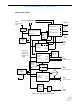
Charger Pre-Regulator — The +20 VDC output provides up to 60 W of battery charging power.
This DC output voltage is then used as the main power source for charging batteries. The circuit
uses a single-ended flyback converter topology. This pre-regulator circuit is active at all times
when the 90367/90369 is powered from the external power supply voltage.
Charger CPU IC — This IC is a pre-programmed microprocessor designed specifically for
controlling the charging of batteries. The CPU monitors the voltage and resistance of the batteries
while charging and determines when to turn the charger power converter ON or OFF. It also can
detect faulty batteries. The CPU also periodically performs maintenance cycles to keep batteries
fully charged.
Charger Power Converter — The power converter consists of a LT1511 step down converter and
various discrete components. It is turned ON and OFF under the control of the charger CPU IC.
When ON, it charges the batteries with a maximum current that is allowed by the charge rate
control circuit.
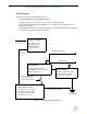
Charge Rate Control — The minimum battery charge rate is always controlled by the battery
itself. A battery will only accept the current it is capable of converting to charge inside the cells.
However, the control for the maximum battery charge current is controlled in one of two ways. If
the 90367/90369 unit is powered from the power supply and the front panel switch is OFF, the
maximum charge current defaults to the maximum current that the batteries can take, which is
1.8 A. If the 90367/90369 unit is powered from the AC/DC power supply and the front panel switch
is ON, the CPU will have control of the maximum battery charge rate via an analog switch and
digital potientometer. The CPU monitors the power consumed by the monitor electronics and
adjusts the charge current based on the amount of remaining power available from the power
supply.
Battery Charging LED Flasher — This is a simple op-amp oscillator circuit that controls the
behavior of the front panel LED. When the batteries are charging, a signal from the battery
charging circuits causes the oscillator to run, which causes the front panel LED to flash. When the
AC/DC power supply is present and the batteries are not charging, the front panel LED is forced
continuously ON. The front panel LED is OFF when the unit is not powered from the AC power
supply. The front panel switch has no control over the front panel LED.
Battery Fault/Interrupt Signal — If the battery voltage exceeds the upper limit, the charger CPU
IC will power OFF the charger and then attempt to charge again. If the battery voltage exceeds the
upper limit again, a 1 Hz signal will be sent to an MPC860 CPU interrupt input (via the ISA bridge).
The software will sense this 1 Hz rate and will indicate a battery failure. If the battery voltage is too
low, the process is the same.
Automatic Fan Control — The MPC860 CPU monitors internal temperature via temperature
sensors and an A/D. If the temperature exceeds a preset limit, the CPU will run the fan at a normal
speed until the temperature is reduced. However, during battery charging, the battery chargers
override the CPU and force the fan on at a higher than normal speed. This allows the battery
chargers to run at full output without overheating the unit.
Note:
Fan will not operate unless a battery is plugged in.