
Service manual


Ultraview 1030/1050 Monitors — Service Manual
4-12
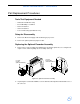
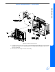
Removing the Chassis Assembly
The chassis assembly includes the sheet metal Interconnect PCBA, and the fan/battery
connection assembly.
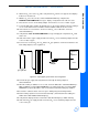
Figure 4-4: Chassis assembly for Ultraview 1030/1050
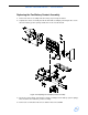
1 Remove the I/O option panel, bezel, main PCBA, module, and optional recorder and CPU as
previously described.
2 Place the monitor face down with the bottom facing you.
3 Remove the screw near the ground terminal area.
4 Remove the two screws with washers from the option area.
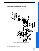
Note:
These washers must be used when replacing the screws. If they are left out, the screws will
penetrate into the battery chassis and interfere with the battery clearance.
5 Remove the four 6-32 × 0.375 inch screws from the bottom of the monitor.
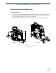
6 Turn the assembly over and remove the two top screws to secure the wall of the module
compartment to the rear housing.