USER MANUAL Models: CVG-719xl, Presentation Switcher / Scaler CVG-720xl, Presentation Switcher / Scaler CVG-724xl, Presentation Switcher / Scaler
Contents 1 2 3 4 5 6 6.1 6.2 7 7.1 7.2 Introduction Getting Started Overview Your Presentation Switcher / Scaler Installing on a Rack Connecting your Presentation Switcher / Scaler The RGBS and RGsB PINOUTs Connecting a PC Presentation Switcher / Scaler Buttons Switching an Input The PIP Button Feature 1 1 1 3 9 10 11 13 14 14 15 7.3 7.4 8 8.1 8.2 8.3 8.
10 CVG-724xl Communication Protocol 45 Figures Figure 1: CVG-719xl Presentation Switcher / Scaler Front Panel Figure 2 CVG-719xl Presentation Switcher / Scaler Rear Panel Figure 3: CVG-720xl Presentation Switcher / Scaler Front Panel Figure 4: CVG-720xl Presentation Switcher / Scaler Rear Panel Figure 5: CVG-724xl Presentation Switcher / Scaler Front Panel Figure 6: CVG-724xl Presentation Switcher / Scaler Rear Panel Figure 7: Connecting the CVG-724xl Rear Panel Figure 8: Connecting the PC Figure 9: OSD
Tables Table 1: Front Panel Presentation Switcher / Scaler Features Table 2: Rear Panel Presentation Switcher / Scaler Features Table 3: RGBS and RGsB PINOUTS Table 4: PIP Source Appearance Availability Table 5: Infra-Red Remote Control Transmitter Functions Table 6: Brightness and Contrast Screen Functions Table 7: Gamma and Color Screen Functions Table 8: Geometry Scale Functions Table 9: Geometry Zoom Functions Table 10: Graphic Setting Utility Screen Features Table 11: Video Setting Utility Screen Featu
1 Introduction Congratulations on purchasing your CVG-719xl / CVG -720xl / CVG -724xl Presentation Switcher / Scaler, which is ideal for the following typical applications: Projection systems in conference rooms, boardrooms, auditoriums, hotels and churches Production studios, rental and staging Any application where high quality conversion and switching of multiple and different video signals to graphical data signals is required for projection purposes The package includes the following items: CVG-719xl
VGA (640x480) 852x1024i 720x483 SVGA (800x600) 1024x1024i 852x480 XGA (1024x768) 1366x768 1400x1050 SXGA (1280x1024) 1365x1024 1280x768*1 UXGA (1600x1200) 1280x720 User Define2 The CVG -724xl also has the following user selectable output pixel rates: 480p, 720p, 1080i and 1080p.
Has two HD15F outputs, that can be used as graphics, or HDTV1 outputs Incorporates full ProcAmp2 for video correction and enhancement Offers high quality de-interlacing 3:2/2:2 pulldown3 Can provide non-linear scaling for 4:3, 16:9 transformation4 Supports firmware upgrade via RS-232 Includes non-volatile memory that retains the last setting, after switching the power off and then on again Includes a built-in Picture-in-Picture (PIP) inserter (not available on the CVG-719xl) Control your Presentation Switch
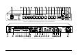
Figure 1: CVG-719xl Presentation Switcher / Scaler Front Panel1 Figure 2 CVG-719xl Presentation Switcher / Scaler Rear Panel2 1 Items 10 and 11, which appear in Table 1 are not included in this machine 2 Items 10 and 15, which appear in Table 2 are not included in this machine 4
Figure 3: CVG-720xl Presentation Switcher / Scaler Front Panel1 Figure 4: CVG-720xl Presentation Switcher / Scaler Rear Panel2 1 Item 10, which appears in Table 1 is not included in this machine 2 Items 10 and 15, which appear in Table 2 are not included in this machine 5
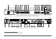
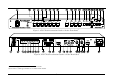
Figure 5: CVG-724xl Presentation Switcher / Scaler Front Panel Figure 6: CVG-724xl Presentation Switcher / Scaler Rear Panel 6
Table 1: Front Panel Presentation Switcher / Scaler Features 6 7 8 9 10 Feature POWER Switch IR Receiver / LED AV1 AV2 YC1 INPUT SELECTOR 1 Buttons # 1 2 3 4 5 YC2 COMPONENT DVI 2 VGA 1 2 VGA 2 3 11 12 13 PIP Button BLANK Button MUTE Button 14 15 16 17 18 19 20 21 FREEZE Button MENU Button ENTER Button - Button DOWN Button UP Button + Button RESET TO VGA Button 22 PANEL LOCK Button Function Illuminated switch for turning the machine ON or OFF Red when the unit accepts IR remote commands Press to
Table 2: Rear Panel Presentation Switcher / Scaler Features Feature VIDEO OUT 1 HD15 Connector Function Connects to the video acceptor (for example, a plasma display, projector or monitor) that displays the scaled output In the default HDTV mode, the signal goes out via 3 PINS: PIN 1 is Pr, PIN 2 is Y, PIN 3 is Pb 2 VIDEO OUT 2 HD15 Connector Connects to the video acceptor (for example, a plasma display, projector or monitor) that displays the scaled output In the default HDTV mode, the signal goes out
5 Installing on a Rack This section describes what to do before installing on a rack and how to rack mount. Before Installing on a Rack How to Rack Mount To rack-mount a machine: Before installing on a rack, be sure that the environment is within the recommended range: 1 Attach both ear brackets to the machine. To do so, remove the screws from each side of the machine (3 on each side), and replace those screws through the ear brackets.
6 Connecting your Presentation Switcher / Scaler To connect the CVG-724xl as illustrated in the example1 in Figure 7, do the following2: 1.
4. Connect the LINE AUDIO OUT terminal block connector to one of the audio acceptors, for example, speakers (not illustrated in Figure 7) 5. Connect the SPKR OUT terminal block to a pair of loud speakers. 6. The power cord1 (the power connector is not illustrated in Figure 7). 7. A PC (optional), as section 6.2 describes. 6.
Plasma Display Display Composite Video Player Figure 7: Connecting the CVG-724xl Rear Panel 12 RS-232
6.2 Connecting a PC You can connect a PC (or other controller) to the CVG-724xl via the RS-232 port for remote control, and for upgrading the firmware.
7 Presentation Switcher / Scaler Buttons The CVG-724xl includes the following front panel buttons: Eight INPUT SELECTOR buttons1, see section 7.1 A PIP button2, see section 7.2 BLANK, MUTE and FREEZE buttons Six OSD buttons A RESET TO VGA button A PANEL LOCK button, see section 7.3 7.1 Switching an Input Each INPUT SELECTOR button can be used to select the source. It can also be programmed to freeze the image or display a blank screen when pressed again. Refer to section 8.5.9 for details.
7.2 The PIP Button Feature The Picture-in-Picture inserter (PIP) is used to present video and graphic sources simultaneously. You can display: An inserted video source1 PIP over a graphic source2 display An inserted graphic source2 PIP over a video source1 display 7.2.1 Selecting the PIP Source To use the PIP feature, set the PIP source via the OSD menu by using either the OSD front-panel buttons or the remote-transmitter keys. To set the PIP source, do the following: 1. Select an input source3. 2.
When selecting one PIP source, the Presentation Switcher / Scaler automatically recognizes and displays the selected graphic PIP source on all the video displays1 and the selected video source on all the graphic1 displays, compliant to Table 4.
7.2.4 Toggling between the PIP and the Screen Source (SWAP) To toggle back and forth between the PIP Source and the main display, do the following: Press the SWAP key on the infra-red remote control transmitter (see Figure 14). The OSD SWAP status appears superimposed over the top right corner of the screen for a few seconds1 only when the Source Prompt is ON, as Figure 11 illustrates.
PIP Auto(NTSC VGA-2 System) Source: Figure 12: PIP Size – Split Screen 7.2.5.2 Moving the Position of the PIP To move the position of the PIP, as illustrated in Figure 13, use the OSD menu (Utility>>PIP Setting>>H-Position; V-Position). When the Source Prompt is ON, and the PIP Frame is ON, you can instantly position the PIP using the preset position control keys on the infra-red remote control transmitter. When there is no orange frame, use the +, -, Up and DOWN buttons1.
7.3 Locking and Unlocking the Front Panel You can lock the front panel1 to safeguard the settings on the CVG-724xl.
Figure 14: Infra-Red Remote Control Transmitter 20
Table 5: Infra-Red Remote Control Transmitter Functions Keys OUT FREEZE POWER 1 INPUT SELECTOR INFO. PRESET POSITION 2 CONTROL AUTO IMAGE MENU 7 NAVIGATION CONTROL AUTO GAIN 8 SWAP 9 PIP CONT. BRIGHT. AUDIO/ZOOM CONTROL7 MODE SCALE Function Selects the output resolution Pauses the output video Cycles power 8 separate keys for selecting each of the following sources: AV1, AV2, COMP.
8 Configuring the CVG-724xl via the OSD MENU Screens The OSD superimposes a menu on the screen from which you can configure and control each input signal on your CVG-724xl, using the MENU, ENTER, , +, UP and DOWN OSD buttons on the front panel and the remote transmitter. To use the OSD menus: 1. Select the desired input signal. 2.
8.1 Controlling the Brightness and Contrast Figure 17 and Table 6 define the Brightness and Contrast screen.
8.2 Controlling the Gamma and Color Figure 18 and Table 7 define the Gamma and Color Screen.
8.3 Selecting the Source Figure 19 illustrates the Source screen, displaying the active source1 (main screen). Scroll up and down to change the source (same as selecting an INPUT with the remote transmitter or via the INPUT SELECTOR buttons). Figure 19: Source Selection Screen 8.4 Controlling the Scale Geometry Figure 20 illustrates the main Geometry Screen, from which you can scale and zoom.
8.4.1 Setting the Scale Features Figure 21 (for a graphic source), Figure 22 (for a video source) and Table 8 define the Scale feature on the main Geometry screen.
Table 8: Geometry Scale Functions Button Aspect Ratio 6 Non-Linear 8.4.
The zoom ratio and the zoom position are illustrated by a small rectangle inside a transparent pop-up OSD Enlarge status box that appears at the top right corner of the screen, as the example in Figure 24 illustrates: Enlarge x 400% Auto(NTSC Sys tem) Figure 24: OSD Enlarge Status When you change the zoom ratio or zoom position, the screen image is adjusted accordingly, and the change is reflected in the pop-up OSD Enlarge status box. 8.4.2.
8.4.2.
8.5 Configuring via the Utility Screens Figure 29 shows the Utility menu, from which you can define the machine settings. Figure 29: Utility Screen 8.5.1 Choosing the Graphic Utility Settings From the Graphic1 Setting Utility screen (see Figure 30), you can set the color format, position, Color, hue, sharpness, frequency and phase, as well as auto image and auto gain (described in Table 10). Figure 30: Graphic Setting Utility Screen 1 When a VGA source is selected, “Graphic Setting” will be shown.
Table 10: Graphic Setting Utility Screen Features Button Function Range Default Color Format Selecting the color format lets you select RGB or YUV1 colorspace.
8.5.3 Choosing the Audio Utility Settings From the Audio Setting Utility screen (see Figure 32), you can set the volume, treble, bass, and choose between stereo and mono.
Table 13: PIP Setting Utility Screen Features Button PIP On/Off Function Activate or deactivate the PIP feature Range PIP Source Select the PIP source, as described in section 7.2.
8.5.6 Choosing the OSD Utility Settings Figure 35 and Table 15 define the OSD Setting Utility screen.
8.5.7 Choosing the Output Utility Settings Figure 36 and Table 16 define the Output Utility settings. From the Output Setting Utility screen, you can set the Resolution, Refresh Rate, and a user definable output mode (see Figure 38 and Table 17).
8.5.7.1 The User Mode Setting Figure 38 and Table 17 define the User Mode Setting1.
8.5.8 Choosing Factory Reset From the Factory Reset Utility screen (see Figure 39), you can reset your CVG-724xl to its preset default setting: Figure 39: Factory Reset Utility Screen 8.5.9 Choosing Advanced Utility Settings Figure 40 and Table 18 define the Advanced Utility screen.
Table 18: Advanced Utility Screen Features Button Input Button Startup Logo Function You can set the function of the input button besides selecting the input signal: Freeze/Blank (press selected input button once to freeze the frame, press again to create a blank screen and again to return to normal state); Freeze (press once to freeze the frame, press again to cancel freeze); Blank (press once to insert blank screen, press again to return to display); Ignore (input button ignores freeze and blank – you c
Table 19: Mode Define Features H Total Mode Define Definitions Horizontal total H Start Horizontal active start point H Active Horizontal active region V Start Vertical active start point V Active Ch. Pump Vertical active region Charge pump current Color Color format H Freq Horizontal Frequency V Freq Vertical Frequency V Total Vertical total Save Mode Save the user defined resolution1 Erase Mode Erase the user defined resolution Measure Mode Select between Default and User Define 8.
Non-standard Resolution Figure 43: Non-standard Resolution in the Information Screen 8.
9 Technical Specifications Table 20 includes the technical specifications: 1 Table 20: Technical Specifications of the Presentation Switchers / Scalers INPUTS: MAX. OUTPUT LEVEL: OUTPUTS: OUTPUT RESOLUTIONS: CONTROL: ADDITIONAL CONTROLS: POWER SOURCE: DIMENSIONS: WEIGHT: ACCESSORIES: 2 x CV 1 Vpp/75 on RCA connectors; 2 x Y/C (s-Video) 1 Vpp (Y), 0.
Sync Type Support RGB Signal Resolution 800x600 RGBHV, RGBHs, RGsB (not supported) Vertical Frequency (Hz) Horizontal Frequency (kHz) 85 53.674l 832x624 832x624 75 49.7001 1024x800 1024x800 84 70.8401 1024x768 1024x768 60 48.363l 1024x768 70 56.476l 1024x768 75 60.200l 1024x768 85 68.677l 1152x864 1152x864 75 67.500l 1152x870 1152x870 75 68.700l 1152x900 1152x900 66 61.846l 1280x960 1152x900 1280x960 76 60 71.808l 60.000l 1280x960 85 85.
Table 22: Technical Specifications of the DVI Input Signal DVI Signal 640x480 Resolution 640x480 Vertical Frequency (Hz) 60 Horizontal Frequency (kHz) 31.469l 640x480 67 35.0 640x480 72 37.861l 640x480 75 37.500l 720x400 640x480 720x400 85 70 43.269l 31.469l 720x400 85 37.92 800x600 800x600 56 35.156l 800x600 60 37.879l 800x600 72 48.077 800x600 75 46.875l 800x600 85 53.674l 1024x768 60 48.363l 1024x768 70 56.476l 1024x768 75 60.
Table 24: Technical Specifications of the HDTV Input Signal HDTV mode DVI Signal 1080i Resolution 1920x540 1080i, 720p, 480p, 576p, 1024x576p Vertical Frequency (Hz) Horizontal Frequency (kHz) 60 33.6701 Remarks YPbPr 720p 1920x540 1280x720 50 60 28.1251 45.363l YPbPr YPbPr 1280x720 50 37.500l YPbPr 480p 720x483 60 31.469l YPbPr 576p 720x576 50 31.256l YPbPr 1024x576p 1024x576 50 31.256l YPbPr 576i 720x275 50 15.600l YCbCr 480i 720x235 60 15.
10 CVG-724xl Communication Protocol This protocol includes two types of commands: 3 bytes and 4 bytes. In the 3 bytes command type, the scaler operates in a fast mode because it does not save the information immediately. The sent command is executed immediately, but the status of the scaler is saved in the non-volatile memory only after 30 sec of no activity. In the 4 bytes command type, the scaler executes the save process immediately after each command.
Control Type 0 0 0 0 0 0 0 0 0 0 0 0 0 0 0 0 0 0 0 0 0 0 0 0 0 0 0 0 0 0 0 0 0 0 0 0 0 0 0 0 1: Set 2: Get 1: Set 2: Get 1: Set 2: Get Function 0 1 2 3 4 5 6 7 8 9 10 11 12 13 14 15 16 17 18 19 20 21 22 23 24 25 26 27 28 29 30 31 32 33 34 35 36 37 38 39 0 1 2 Function Param (for Set) Description N/A Output N/A Freeze N/A Power N/A AV1 N/A AV2 N/A Comp N/A YC1 N/A YC2 N/A VGA1 N/A VGA2 (CVG-724xl Only) N/A DVI N/A Information N/A Area Left Up N/A Area Middle Up N/A Area Right Up N/A Area Left Center N/A Ar
Control Type 1: Set 2: Get 1: Set 2: Get 1: Set 2: Get 1: Set 2: Get 1: Set 2: Get 1: Set 2: Get 1: Set 2: Get 1: Set 2: Get 1: Set 2: Get 1: Set 2: Get 1: Set 2: Get 1: Set 2: Get 1: Set 2: Get 1: Set 2: Get 1: Set 2: Get 1: Set 2: Get 1: Set 2: Get 1: Set 2: Get 1: Set 2: Get 1: Set 2: Get 1: Set 2: Get 1: Set 2: Get 1: Set 2: Get 1: Set 2: Get 1: Set 2: Get 1: Set 2: Get Function Function Description Param (for Set) 3 0~127 4 0~32 5 0~32 6 0~32 7 0~32 8 -10~10 9 0~127 10 0~127 11 0~1
Control Type 1: Set 2: Get 1: Set 2: Get 1: Set 2: Get 1: Set 2: Get 1: Set 2: Get Function 29 0~127 30 0~127 31 0~16 32 0~20 0~20 33 0~39 1: Set 2: Get 1: Set 2: Get 1: Set 2: Get 1: Set 2: Get 1: Set 2: Get 1: Set 2: Get 1: Set 2: Get 1: Set 2: Get 1: Set 2: Get 1: Set 2: Get Function Description Param (for Set) Video Setting: Color Video Setting: Hue Video Setting: Sharpness Video Setting: H-Position Video V-Position for NTSC/NTSC 4.43/PAL-M/PAL 60 Video V-Position for PAL/PALN/SECAM/NTSC 4.
Control Type Function Param (for Set) 3:Set 4:Get 3 0~5 3: Set 4: Get 4 0~10 3: Set 4: Get 5 0~2 3: Set 4: Get 6 0~2 3: Set 4: Get 7 0~6 8 0~1 9 0~1 10 0~1 3: Set 4: Get 3: Set 4: Get 3: Set 4: Get Function Description 0: Full Screen 1: Native Geometry: 2: NonLinear VGA Aspect Ratio 3: 4:3 4: 16:9 5: UserDefine 0: Off 1: 150% 2: 200% 3: 225% 4: 250% Zoom: 5: 275% Zoom Ratio 6: 300% 7: 325% 8: 350% 9: 375% 10: 400% 0: Default Graphics Setting: 1: RGB Color Format 2: YUV 0: Default Vi
Control Type 3: Set 4: Get Function Param (for Set) Function Description 0: Fast Seamless Switch: 1: Moderate Mode 2: Safe Seamless Switch: 0: Black Background 1: Blue Seamless Switch: 0: Off Auto Search 1: On 0: Off OSD Setting: Startup Logo 1: On 0: Normal OSD Setting: Size 1: Double 0: Off OSD Setting: Source Prompt 1: On 0: Blue OSD Setting: Blank Color 1: Black 0: 640x480 1: 800x600 2: 1024x768 3: 1280x1024 4: 1600x1200 5: 852x1024i 6: 1024x1024i 7: 1366x768 8: 1365x1024 9: 1280x720 Output Resolutio
Control Type Function Function Description Param (for Set) 5 2 N/A Load Gamma/Color - Cinema 5 5 5 6: Set 7: Get 6: Set 7: Get 6: Set 7: Get 6: Set 7: Get 3 4 5 N/A N/A N/A Load Gamma/Color - Nature Load Gamma/Color - User1 Load Gamma/Color - User2 0 0~1 Power 1 0~1 Freeze 2 0~1 Blank 3 0~1 Mute 8 0 N/A "Resolution/Refresh Rate" Or "Video Stand" 44 > 100 HT, H-Sync Cycle 45 >0 HW, H-Sync Width 46 >0 HS, Active Pixel Start 47 - HA, Active Pixel 44 > 100 HT, H-Sync Cy