ENT48906 10/15/04 8:12 AM Page b NT® INTEGRATED FLOW CONTROLLER WITH DEVICENET™ COMMUNICATION User Guide
ENT48906 10/15/04 8:12 AM Page c
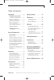
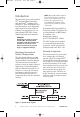
ENT48906 10/15/04 8:12 AM Page 1 NT® INTEGRATED FLOW CONTROLLER WITH DEVICENET™ COMMUNICATION USER GUIDE Table of Contents Introduction .................................. 2 Diagnostic Guide ........................ 17 Identifying Nonstandard Product Configurations .......... 2 Principle of Operation ............... 2 Maintenance ............................... 19 System Block Diagram .............. 2 Factory Configured .................... 3 Control Mode Functions ............ 3 Autozero Function .
ENT48906 10/15/04 8:12 AM Page 2 NT® INTEGRATED FLOW CONTROLLER WITH DEVICENET™ COMMUNICATION USER GUIDE Introduction This manual is for use with standard NT® Integrated Flow Controllers with DeviceNetTM communication, Model 6500. These instruments have been designed for use in high-purity applications in the semiconductor industry. The wetted parts are constructed with PTFE, PFA or other similar high-purity inert materials.
ENT48906 10/15/04 8:12 AM Page 3 NT® INTEGRATED FLOW CONTROLLER WITH DEVICENET™ COMMUNICATION USER GUIDE Factory Configured The standard NT® Integrated Flow Controller is pre-configured from the factory for the flow range specified by the user. The specified flow range is found on the label of the unit. The unit control algorithm uses pressure and flow measurements to ensure proper operation within specification.
ENT48906 10/15/04 8:12 AM Page 4 NT® INTEGRATED FLOW CONTROLLER WITH DEVICENET™ COMMUNICATION USER GUIDE General Considerations NOTE: The flow controller has been factory sealed. Do not attempt to remove the cover of the unit. Any attempt at removal of the unit cover will void the warranty. Ambient Temperature Range The flow controller is designed to operate in room temperature cleanroom environments: 50° to 86°F (10° to 30°C).
ENT48906 10/15/04 8:12 AM Page 5 NT® INTEGRATED FLOW CONTROLLER WITH DEVICENET™ COMMUNICATION USER GUIDE The power supply must provide continuous 1.0 A (nominal) current for each flow controller installed. Peak power consumption is 1.2 A, maximum. The power supply to the flow controller must provide clean power to the unit and must be used only to power similar measurement-type devices. The power supply must not be used to power other inductive loads, such as motors, relays or solenoids.
ENT48906 10/15/04 8:12 AM Page 6 NT® INTEGRATED FLOW CONTROLLER WITH DEVICENET™ COMMUNICATION USER GUIDE DeviceNetTM Module Status LED This LED is labeled ‘Mod’. INTEGRATED FLOW CONTROLLER STATE LED STATE Power off Off No power is applied through DeviceNet™. IFC self-test Flashing red and green IFC is in self-test. IFC operational Green IFC is operating normally. Minor fault Flashing red IFC has detected a recoverable fault.
ENT48906 10/15/04 8:12 AM Page 7 NT® INTEGRATED FLOW CONTROLLER WITH DEVICENET™ COMMUNICATION USER GUIDE DeviceNetTM Node Address Switches Two, ten-position, rotary switches used for configuring the Media Access Control Identifier (MACID) of the flow controller. These switches specify the MACID using decimal representation. One switch specifies the most significant digit (MSD), or tens position of the MACID.
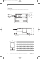
ENT48906 10/15/04 8:12 AM Page 8 NT® INTEGRATED FLOW CONTROLLER WITH DEVICENET™ COMMUNICATION USER GUIDE Dimensions NT® Integrated Flow Controller with DeviceNet™ Communication 0.28″ (7.1 mm) 1.85″ (47.03 mm) 2.87″ (72.9 mm) 7.78″ (197.6 mm) 8.53″ (216.7 mm) 9.05″ (229.9 mm) D A B C Flared nut (2) 2.58″ (65.5 mm) 8 FITTING A B 1⁄4″ C F02 4.63″ (117.5 mm) 4.89″ (124.2 mm) 0.76″ 9.60″ (19.4 mm) (243.8 mm) 3⁄8″ F03 4.63″ (117.5 mm) 4.89″ (124.2 mm) 0.76″ 9.75″ (19.4 mm) (247.
ENT48906 10/15/04 8:12 AM Page 9 NT® INTEGRATED FLOW CONTROLLER WITH DEVICENET™ COMMUNICATION USER GUIDE Installation Provided Equipment = CAUTION! Do not tighten the nuts that protect the flared tube connections during shipment. (See Prepare Fluid Lines on page 11). Tightening these nuts without the proper tubing installed may damage the unit’s flared tube connections. NOTE: This unit has been assembled and double-bagged under cleanroom conditions.
ENT48906 10/15/04 8:12 AM Page 10 NT® INTEGRATED FLOW CONTROLLER WITH DEVICENET™ COMMUNICATION USER GUIDE Mounting Requirements The flow controller may be mounted in any orientation. The unit does not require straight lengths of tubing at the inlet or the outlet connection. Mount the Unit The flow controller and base bracket assembly must be mounted to a solid surface to ensure stability. Verify the valve and the electrical cable are free from mechanical stress from the surrounding equipment.
ENT48906 10/15/04 8:12 AM Page 11 NT® INTEGRATED FLOW CONTROLLER WITH DEVICENET™ COMMUNICATION USER GUIDE Mechanical Installation The standard NT® Integrated Flow Controller must be used with the proper tubing size and fittings. To prepare the fluid lines, begin by sliding the supplied nuts onto the fluid tube. NOTE: Flare each tube end prior to installation onto the valve fitting. CAUTION! Over-tightening of the nuts will result in damage to the fitting.
ENT48906 10/15/04 8:12 AM Page 12 NT® INTEGRATED FLOW CONTROLLER WITH DEVICENET™ COMMUNICATION USER GUIDE Electrical Connections When installing flared tubing to the flow controller, the flared tube is pushed over the valve’s fitting until the fitting reaches the smaller tube diameter. The amount of torque required to tighten the nut is dependent upon the size of the fitting. FITTING SIZE 1⁄4″ 3⁄8″ 1⁄2″ 3⁄4″ Torque (in•lbs.) 5 8 11 14 Torque (N•m) 0.56 0.90 1.24 1.
ENT48906 10/15/04 8:12 AM Page 13 NT® INTEGRATED FLOW CONTROLLER WITH DEVICENET™ COMMUNICATION USER GUIDE DeviceNetTM Cable Cable materials are constructed with 22 AWG wire and a PVC jacket. The connector is a 5-pin, micro-style, 12 mm, male type. FUNCTION PIN ASSIGNMENT COLOR Drain 1 Bare wire V+ 2 Red V- 3 Black CAN_H 4 White CAN_L 5 Blue NOTE: The allowable torque on the 8-32 × 1⁄2” PVDF screws used to secure the clear switch access cover is 7 Newton-centimeters.
ENT48906 10/15/04 8:12 AM Page 14 NT® INTEGRATED FLOW CONTROLLER WITH DEVICENET™ COMMUNICATION USER GUIDE Unit Operation Operating Environment Operating Temperature The flow controller is designed to operate in ambient temperature, cleanroom environments. The unit is specified to operate at temperatures between 50° and 149°F (10° and 65°C).
ENT48906 10/15/04 8:12 AM Page 15 NT® INTEGRATED FLOW CONTROLLER WITH DEVICENET™ COMMUNICATION USER GUIDE Flow Accuracy Minimum Operating Pressure The accuracy of the flow measurement is ±1% of full scale from 20100% of the flow range. The accuracy of the flow measurement is ±2.5% of full scale from 10-20% of the flow range. The accuracy specification includes the effects of linearity, hysteresis and repeatability, using deionized water at 73°F (23°C).
ENT48906 10/15/04 8:12 AM Page 16 NT® INTEGRATED FLOW CONTROLLER WITH DEVICENET™ COMMUNICATION USER GUIDE Warm-up Time Enclosure Integrity The flow controller requires a warmup time of 10 minutes after power is applied. Warm-up time is typically not required if the unit was operated within 3 hours. Momentary immersion and spray down of the flow controller will not affect the performance per NEMA 5 and IP56.
ENT48906 10/15/04 8:12 AM Page 17 NT® INTEGRATED FLOW CONTROLLER WITH DEVICENET™ COMMUNICATION USER GUIDE Diagnostic Guide SYMPTOM POSSIBLE CAUSES SUGGESTIONS 1. Flow reading is very low. The unit is installed backwards. Install the unit so the inlet flow is plumbed on the same side as the electrical connection. Insufficient line pressure. The inlet pressure must be at least 10 PSIG (69 kPa) greater than the outlet pressure.
ENT48906 10/15/04 8:12 AM Page 18 NT® INTEGRATED FLOW CONTROLLER WITH DEVICENET™ COMMUNICATION USER GUIDE Diagnostic Guide (continued) SYMPTOM POSSIBLE CAUSES SUGGESTIONS 6. Flow rate is not meeting desired set point within 10 seconds or longer. The unit is receiving a set point signal with no fluid flow present. The flow controller valve is moved to the full-open position.
ENT48906 10/15/04 8:12 AM Page 19 NT® INTEGRATED FLOW CONTROLLER WITH DEVICENET™ COMMUNICATION USER GUIDE Maintenance Normal Operation During normal operation, the standard NT® Integrated Flow Controller with DeviceNetTM communication requires no maintenance, other than a periodic re-zero of the unit. Re-zero Function The no flow calibration of the flow controller can be re-zeroed, meaning that the flow output that corresponds to zero flow may be reset.
ENT48906 10/15/04 8:12 AM Page 20 NT® INTEGRATED FLOW CONTROLLER WITH DEVICENET™ COMMUNICATION USER GUIDE Reference Physical Specifications PART CONSTRUCTION MATERIALS Wetted parts: Body: Diaphragms: Sensor interface: O-rings: Nonwetted parts: Connection type: Enclosure: PTFE PTFE PFA or CTFE Kalrez® 4079 Polypropylene cover and base plate, Viton® plugs Flaretek® tube fitting NEMA 5/IP54 Power Cable Specifications Input voltage: Input current: Electrical connection: 24 VDC, ±10% 1.0 A nominal, 1.
ENT48906 10/15/04 8:12 AM Page 21 NT® INTEGRATED FLOW CONTROLLER WITH DEVICENET™ COMMUNICATION USER GUIDE Ordering Information MODEL 6500 PRODUCT DESCRIPTION CODE ELECTRICAL CONNECTOR TYPE Integrated Flow Controller AM6 PVC-jacketed 6′ cable set AM12 PVC-jacketed 12′ cable set CODE SET POINT INPUT SIGNAL, CONTROLLER TYPE CODE FLOW RANGE T0 T1 T2 T3 T4 T5 T6 T7 T8 T9 CODE 0-50 ml/min. 0-125 ml/min. 0-250 ml/min. 0-500 ml/min. 0-1250 ml/min. 0-2.5 l/min. 0-5 l/min. 0-10 l/min. 0-20 l/min.
ENT48906 10/15/04 8:12 AM Page 22 NT® INTEGRATED FLOW CONTROLLER WITH DEVICENET™ COMMUNICATION USER GUIDE Certifications ODVA Conformance CE Compliance Entegris products have been tested to various test standards required by the EMC 89/336/EEC directive. The results of this testing are on file at Entegris and are available upon request. Please contact the factory for the latest information. The most current specifications may be found on the Internet at: http://www.entegrisfluidhandling.com.
ENT48906 10/15/04 8:12 AM Page 23 NT® INTEGRATED FLOW CONTROLLER WITH DEVICENET™ COMMUNICATION USER GUIDE DeviceNetTM Communication Integrated Flow Controller Device Device Type: 00 hex controlled to the set point. This vendor specific device profile is based on the DeviceNetTM Fluid Flow Controller (FFC) device profile. The device type is 00 due to the prerelease status of the FFC profile. Type 00 is a Generic Device type. This chapter contains two primary sections.
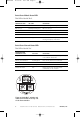
ENT48906 10/15/04 8:12 AM Page 24 NT® INTEGRATED FLOW CONTROLLER WITH DEVICENET™ COMMUNICATION USER GUIDE DeviceNet™ Communication Hierarchy of Semiconductor Equipment Device Objects S-Analog Sensor Class S-Single Stage Controller Pressure S-Analog Actuator Flow S-Sensor Calibration S-Device Supervisor Identity Message Router Assembly DeviceNet™ Connection Class I/O Explicit Message DeviceNet™ Figure 3.
ENT48906 10/15/04 8:12 AM Page 25 NT® INTEGRATED FLOW CONTROLLER WITH DEVICENET™ COMMUNICATION USER GUIDE How Objects Affect Behavior OBJECT AFFECT ON BEHAVIOR Identity Supports the Reset service. Upon receipt of a Reset Service Request of any Type, the Identity Object sends a Reset Service Request to the S-Device supervisor.
ENT48906 10/15/04 8:12 AM Page 26 NT® INTEGRATED FLOW CONTROLLER WITH DEVICENET™ COMMUNICATION USER GUIDE Vendor Specific Section This section specifies the Vendor Specific attributes, service and behaviors supported by this device. It is provided primarily to specify which attributes and services are supported and with what ranges. NOTE: Specific definitions of attributes and services are included here for reference only.
ENT48906 10/15/04 8:12 AM Page 27 NT® INTEGRATED FLOW CONTROLLER WITH DEVICENET™ COMMUNICATION USER GUIDE Instance 1 ATTRIBUTES 1.1 - INSTANCE ATTRIBUTES - IDENTITY OBJECT 1 ATT.
ENT48906 10/15/04 8:12 AM Page 28 NT® INTEGRATED FLOW CONTROLLER WITH DEVICENET™ COMMUNICATION USER GUIDE SERVICES 1.1 - INSTANCES SERVICES - IDENTITY OBJECT 1 CODE REQUIRED SUPPORTED 0Ehex Required Yes 05hex Required Yes NAME PARAMETER VALUES PARAMETERS DESCRIPTION Get_Attribute_ Single Attribute ID (USINT) Retrieves an attribute value Reset Type (USINT) Emulates power Type 0 = Reset. cycling the device.
ENT48906 10/15/04 8:12 AM Page 29 NT® INTEGRATED FLOW CONTROLLER WITH DEVICENET™ COMMUNICATION USER GUIDE DeviceNetTM Object (03hex) Class ATTRIBUTES 3.0 - CLASS ATTRIBUTES - DEVICENET™ OBJECT ATT. ID REQUIRED SUPPORTED ACCESS RULE 1 Optional Yes Get NAME DATA TYPE ATTRIBUTE DESCRIPTION VALUES Revision UINT Object revision = 02 SERVICES 3.
ENT48906 10/15/04 8:12 AM Page 30 NT® INTEGRATED FLOW CONTROLLER WITH DEVICENET™ COMMUNICATION USER GUIDE SERVICES 3.
ENT48906 10/15/04 8:12 AM Page 31 NT® INTEGRATED FLOW CONTROLLER WITH DEVICENET™ COMMUNICATION USER GUIDE SERVICES 4.
ENT48906 10/15/04 8:12 AM Page 32 NT® INTEGRATED FLOW CONTROLLER WITH DEVICENET™ COMMUNICATION USER GUIDE Instances 1-n ATTRIBUTES 4.N - INSTANCE ATTRIBUTES - ASSEMBLY OBJECT ATT. ID REQUIRED SUPPORTED ACCESS RULE NAME 3 Required Get Yes Data ATTRIBUTE DESCRIPTION The I/O Assembly DATA attribute is formatted as a structure of data elements with the First element (elements are listed in the "Instance Identifiers" table) ordered first.
ENT48906 10/15/04 8:12 AM Page 33 NT® INTEGRATED FLOW CONTROLLER WITH DEVICENET™ COMMUNICATION USER GUIDE Instance 1 - Explicit ATTRIBUTES 5.1 - INSTANCE ATTRIBUTES - CONNECTION OBJECT 1 ATT.
ENT48906 10/15/04 8:12 AM Page 34 NT® INTEGRATED FLOW CONTROLLER WITH DEVICENET™ COMMUNICATION USER GUIDE SERVICES 5.
ENT48906 10/15/04 8:12 AM Page 35 NT® INTEGRATED FLOW CONTROLLER WITH DEVICENET™ COMMUNICATION USER GUIDE SERVICES 5.
ENT48906 10/15/04 8:12 AM Page 36 NT® INTEGRATED FLOW CONTROLLER WITH DEVICENET™ COMMUNICATION USER GUIDE Instance 1 ATTRIBUTES 30.1 - INSTANCE ATTRIBUTES - S-DEVICE SUPERVISOR OBJECT 1 ATT. REID QUIRED SUPACCESS PORTED RULE NV NAME DATA TYPE ATTRIBUTE DESCRIPTION VALUES 3 Required Yes Get NVC Device Type SHORT STRING ASCII Text, Max.
ENT48906 10/15/04 8:12 AM Page 37 NT® INTEGRATED FLOW CONTROLLER WITH DEVICENET™ COMMUNICATION USER GUIDE ATT.
ENT48906 10/15/04 8:12 AM Page 38 NT® INTEGRATED FLOW CONTROLLER WITH DEVICENET™ COMMUNICATION USER GUIDE ATT.
ENT48906 10/15/04 8:12 AM Page 39 NT® INTEGRATED FLOW CONTROLLER WITH DEVICENET™ COMMUNICATION USER GUIDE SERVICES 3.
ENT48906 10/15/04 8:12 AM Page 40 NT® INTEGRATED FLOW CONTROLLER WITH DEVICENET™ COMMUNICATION USER GUIDE S-Analog Sensor Object (31hex) Class ATTRIBUTES 31.0 - CLASS ATTRIBUTES - S-ANALOG SENSOR OBJECT ATT. ID REQUIRED SUPPORTED ACCESS RULE 1 Optional Yes Get NAME DATA TYPE ATTRIBUTE DESCRIPTION VALUES Revision UINT Object revision = 01 SERVICES 31.
ENT48906 10/15/04 8:12 AM Page 41 NT® INTEGRATED FLOW CONTROLLER WITH DEVICENET™ COMMUNICATION USER GUIDE ATT.
ENT48906 10/15/04 8:12 AM Page 42 NT® INTEGRATED FLOW CONTROLLER WITH DEVICENET™ COMMUNICATION USER GUIDE ATT. REID QUIRED SUPACCESS PORTED RULE NV NAME DATA TYPE ATTRIBUTE DESCRIPTION VALUES 35 Optional Yes Set NV Gas Calibration Object Instance UINT Indicates which Gas Calibration object instance is active for this object. 00 = Disabled 01 = Enable [default] NOTE: This default is a DeviceNet™ compliance variance. 99 Cond.
ENT48906 10/15/04 8:12 AM Page 43 NT® INTEGRATED FLOW CONTROLLER WITH DEVICENET™ COMMUNICATION USER GUIDE Instance 2 - Inlet Pressure ATTRIBUTES 31.2 - INSTANCE ATTRIBUTES - S-ANALOG SENSOR OBJECT 2 ATT. REID QUIRED SUPACCESS PORTED RULE NV NAME DATA TYPE ATTRIBUTE DESCRIPTION Determines the Data Type of value and all related attributes as specified in this table.
ENT48906 10/15/04 8:12 AM Page 44 NT® INTEGRATED FLOW CONTROLLER WITH DEVICENET™ COMMUNICATION USER GUIDE ATT. REID QUIRED SUPACCESS PORTED RULE NV NAME DATA TYPE ATTRIBUTE DESCRIPTION VALUES 22 Optional Yes Set NV Warning Trip Point Low Same as Value Determines the value below which a Warning Condition will occur. [default] = Minimum value for its data type. 25 Optional Yes Set NV Safe State USINT Specifies the behavior for the value for states other than Execute.
ENT48906 10/15/04 8:12 AM Page 45 NT® INTEGRATED FLOW CONTROLLER WITH DEVICENET™ COMMUNICATION USER GUIDE S-Analog Actuator Object (32hex) Class ATTRIBUTES 32.0 - CLASS ATTRIBUTES - S-ANALOG ACTUATOR OBJECT ATT. ID REQUIRED SUPPORTED ACCESS RULE 1 Optional Yes Get NAME DATA TYPE ATTRIBUTE DESCRIPTION VALUES Revision UINT Object revision = 01 SERVICES 32.
ENT48906 10/15/04 8:12 AM Page 46 NT® INTEGRATED FLOW CONTROLLER WITH DEVICENET™ COMMUNICATION USER GUIDE ATT.
ENT48906 10/15/04 8:12 AM Page 47 NT® INTEGRATED FLOW CONTROLLER WITH DEVICENET™ COMMUNICATION USER GUIDE SERVICES 33.0 - CLASS SERVICES - S-SINGLE STAGE CONTROLLER OBJECT CODE REQUIRED SUPPORTED 0Ehex Required Yes NAME Get_Attribute_ Single PARAMETERS DESCRIPTION Attribute ID (USINT) Retrieves an attribute value PARAMETER VALUES 1–255 Instance 1 ATTRIBUTES 33.1 - INSTANCE ATTRIBUTES - S-SINGLE STAGE CONTROLLER OBJECT 1 ATT.
ENT48906 10/15/04 8:12 AM Page 48 NT® INTEGRATED FLOW CONTROLLER WITH DEVICENET™ COMMUNICATION USER GUIDE S-Sensor Calibration Object (64hex) Class ATTRIBUTES 64.0 - CLASS ATTRIBUTES - S-SENSOR CALIBRATION OBJECT ATT. ID REQUIRED SUPPORTED ACCESS RULE 1 Optional Yes Get NAME DATA TYPE ATTRIBUTE DESCRIPTION VALUES Revision UINT Object revision = 01 SERVICES 64.
ENT48906 10/15/04 8:12 AM Page 49 NT® INTEGRATED FLOW CONTROLLER WITH DEVICENET™ COMMUNICATION USER GUIDE ATT. REID QUIRED SUPACCESS PORTED RULE NV DATA TYPE NAME 5 Optional Yes Set NV Calibration SHORT Name STRING 6 Optional Yes Get NVF Full Scale ATTRIBUTE DESCRIPTION STRUCT of: Full scale of the device using this object instance REAL VALUES ASCII text, max 50 [default] = Null characters, User accessible string representation used to identify the calibration or application.
ENT48906 10/15/04 8:12 AM Page 50 NT® INTEGRATED FLOW CONTROLLER WITH DEVICENET™ COMMUNICATION USER GUIDE Repair and Warranty Service Entegris, Inc. warrants each new product against defects in materials and workmanship for 18 months of time from shipment. Entegris makes no warranty, express or implied, with respect to any components, products, information or services provided by any third party.
ENT48906 10/15/04 8:12 AM Page 51 NT® INTEGRATED FLOW CONTROLLER WITH DEVICENET™ COMMUNICATION USER GUIDE Notes ENTEGRIS, INC. Customer Service Tel.
ENT48906 10/15/04 8:12 AM Page a ENTEGRIS, INC. Corporate Headquarters 3500 Lyman Boulevard Chaska, Minnesota 55318 USA Customer Service Tel. 763-502-0200 Toll Free 877-503-0200 Customer Service Fax 763-502-0300 www.entegris.com www.entegrisfluidhandling.com Entegris ® and Flaretek® are registered trademarks of Entegris, Inc. NT® is a registered trademark of NT International, an Entegris Company. Kalrez® and Viton® are registered trademarks of DuPont Dow Elastomers.