
User's Manual

9 0 0 M H Z B I D I R E C T I O N A L A M P L I F I E R T E C H N I C A L M A N U A L
5
Sub B’d Card
LED Alarms
MGC
HPA
DPLX
Power Supply (PSU)
DPLX
Donor
Antenna
(Base)
DAS Service
Antenna
(Mobile)
10,20,
..
1,2,3,..
Det
1,2,3,..
10,20,..
Monitoring & Control Unit
MGC ATT MGC ATT
MGC ATT
MGC ATT
HPA
LNA
LNA
AGC ATT
AGC ATT
AC
DC
Down Link Path
UP Link Path
RS 232USB (Optional)
Clk,Data,En
Det
Clk,Data,En
Det
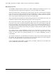
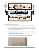
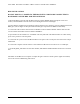
Figure 1: Block diagram of the 900 MHz bidirectional amplifier
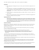
Led Indicator Alarm and Manual Level Control.
- The unit has visual alarms using LED indicators for the following conditions; AGC, S/D and Power.
o AGC: alarm turns red when the AGC is not delivering any attenuation. This can happen in two
situations. Either the AGC is turned off by the user (see monitoring and control section) or if
the signal at input of the DL is too weak. This is not necessarily a failure. It can just be a
warning that the signal from the BTS is too weak.
o S/D: The shutdown indicator turns red when the system is in automatic shutdown. This
happens when the internal temperature is too high or when the output power exceeds the
maximum limit allowed. When the RF module is turned off by the user (see monitoring and
control section) the S/D indicator will start flashing.
o The Power indicator turns red when the RFM is not receiving the correct DC power.