
User's Manual

9 0 0 M H Z B I D I R E C T I O N A L A M P L I F I E R T E C H N I C A L M A N U A L
7
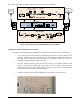
4) Downlink / Uplink AGC Attenuation. Automatic attenuation delivered by the AGC to maintain the
output level constant. When this value shows “0” it is because the input power is lower than -53 dBm. If
it is zero in the Downlink path the AGC alarm will turn red.
5) DC voltage / current monitor. It shows the DC voltage and current to the RF unit.
6) System temp. Shows the current system temperature.
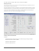
4.2 Alarms:
1) Downlink input over power.
Turns red when the input power from the BTS exceeds the maximum predefined setting.
2) Downlink / Uplink output overload.
3) AGC range alarm.
4) Downlink / Uplink Shutdown. Turns red when a shutdown occurs because of overtemp or being over
the output power limit. It will be flashing when it is shut down by the user.
5) PSU alarm.
6) Over temp. Alarm.
7) Door Alarm.
4.3 Control:
1) Downlink / Uplink HPA on/off
2) Downlink / Uplink gain control
3) Downlink / Uplink AGC on/off
4) Downlink / Uplink shutdown on/off
5) MCU Reset
6) Alarm limit
4.4 Additional Information:
1) Software Version
2) Vendor name
3) Model name
4) Time
5) Alarm history
6) Maintenance history