
User's Manual

9 0 0 M H Z B I D I R E C T I O N A L A M P L I F I E R T E C H N I C A L M A N U A L
9
BDA INSTALLATION
DO NOT APPLY A.C. POWER TO THE BDA UNTIL CABLES ARE CONNECTED TO
BOTH PORTS OF THE BDA AND THE ANTENNAS.
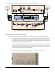
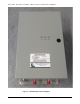
1. Mount the BDA on the wall with the RF connectors pointing DOWN. Using appropriate screws and
anchors, attach the BDA to the wall at the four mounting holes on the side flanges.
2. Ensure that the isolation between the donor antenna and the service antenna is at least 12 dB greater than the
BDA gain. (Use the higher of the Uplink and Downlink gains reported on the BDA test data sheet).
3. Connect the cable from the donor antenna to the BDA connector labeled “BASE” and the cable from the
service antennas to the BDA connector labeled “MOBILE”.
4. Open the door of the metallic box of the BDA and verify that both of the PSU switches are in their factory
preset “ON” positions. Close the panels.
5. Connect the AC power cord to the BDA and then to the power source. Verify that the “Power ON” lamp is
illuminated.
6. Connect the computer with the software v1.02 installed via RS 232 serial connector or via a USB port.
7. On the RF_BDA_GUI make sure that AGC Enable, ASD Enable and HPA Enable functions are all turned
ON.
Installation of the BDA is now complete. To adjust the gain controls to suit the specific signal environment,
refer to the section on Monitoring and Control.