
User's Manual


UHF BI-DIRECTIONAL AMPLIFIER TECHNICAL MANUAL
7
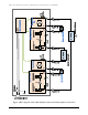
VGA Max Input Level and Optimum Input Level – MSA#1 Setting
The VGA can maintain constant its output power for any composite input level from –60 to -25dBm. If
the input level is too high, the MSA#1 must be used to provide additional attenuation, then decrease the
input signal to the correct level. The MSA#1 attenuation can be set from 0 to 30dB per 2dB step, by
mean of a hexadecimal switch (16 positions from “0” to “F”).
When it is possible, it is recommended to set the nominal input power to -40dBm, such a setting allows
maximum dynamic range of the AGC circuit, and the VGA output power will be constant even if several
sub-carriers are suddenly added on or dropped from the main signal.
The VGA displays two RSSI LED (Received Signal Strength Indicator LED) labeled HI and LOW.
When both LED are on, the input composite power should be with-in the optimum range, .i.e. -42 to -
38dBm.
Thus, if the received nominal input power is ranging from -42 to -8dBm, it is possible to set the VGA
input to the optimum level, by changing the MSA#1 setting from 0 to 30dB of attenuation.
If the received nominal level is lower than -42dBm, the MSA#1 should be set at 0dB attenuation.
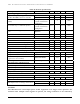
Table I: MSA#1 and MSA#2 attenuation versus
Hexadecimal Rotary Switch Position
Dial
MSA #1
Att. (dB)
MSA #2
Att. (dB)
0 0 0
1 2 1
2 4 2
3 6 3
4 8 4
5 10 5
6 12 6
7 14 7
8 16 8
9 18 9
A 20 10
B 22 11
C 24 12
D 26 13
E 28 14
F 30 15