9070 plus User Manual 78413138-001 Rev. 01 Sett.
Compuprint Products Information Thanks for choosing the Compuprint 9070plus printer models. Your printer is a reliable working equipment that will be very useful in your daily job. Our printers have been designed to be compact and respectful of the work environment. They offer a wide range of features and multiple functions that confirm the high technological level reached by the Sferal printers with Compuprint brand.
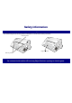
Safety Information Never remove any printer cover. The following areas of the printer should be covered for safety reasons: Rear Plug Cover Large Rear Cover Rear Plug Covers The above openings must always be protected with their cover. Do not touch inside and do not insert any object into these openings or into the gears.
FFC Notes This equipment has been tested and found to comply with the limits for a Class A digital device, pursuant to Part 15 of the FCC Rules. These limits are designed to provide reasonable protection against harmful interference when the equipment is operated in a commercial environment. This equipment generates, uses, and can radiate radio frequency energy and, if not installed and used in accordance with the instruction manual, may cause harmful interference to radio communications.
Table of Contents Compuprint Products Information ....................... ii Safety Information ................................................ iii FFC Notes .............................................................. iv Canadian D.O.C. Radio Interference Regulation iv EEC Regulations ................................................... iv Table of Contents ................................................... v Getting to Know Your Printer ............................... 1 Printer Features ..............
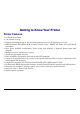
Getting to Know Your Printer Printer Features • • • • • • • • • • • • • • 24 Needle Print Head 136 columns @10 cpi High speed Draft printing at 720 cps, Draft printing at 700 cps, LQ printing at 133 cps IBM Proprinter XL24/XL24 AGM, Personal Printer 2391+, EPSON LQ Series and ANSI X3.
2
Unpacking Your Printer The following items are included in the box: Notify any damage to your supplier.
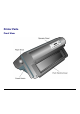
Printer Parts Front View 4
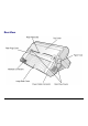
Rear View 5
Setting Up Your Printer Choosing a Suitable Location Consider the following points when you choose the location for your printer: • The distance between the printer and the host computer must not exceed the length of the interface cable; • The location must be sturdy, horizontal and stable; • Your printer must not be exposed to direct sunlight, extreme heat, cold, dust or humidity (see "Printer Specifications" later); • The power outlet must be compatible with the plug of the printer's power cord.
Printer Assembly Removal of the Shipment Locks Open all the printer covers and make sure that you remove all the shipment locks from the printer.
Ribbon Cartridge Installation Make sure that you are using only Compuprint original consumables. 1. Make sure that the printer is turned off. 2.
3. With the printer powered on, enter the OFF LINE status pressing the ON-LINE Key and then checking ON-LINE indicator unlit. 4. Open the top cover using the small handles on either side of the top cover. 5. The print carriage prepares for ribbon cartridge installation.
5. Before installing the ribbon cartridge turn the ribbon-winding knob in the arrow direction (located on the cartridge) to take up slack in the ribbon. Cartridge Pins Ribbon Winding Knob To avoid damage to the ribbon, do not turn the winding knob in the wrong direction. 6. Align the right and left cartridge pins with the printer locking points.
7. Slide and insert the ribbon guide between the print head and the ribbon guide mask holding it perpendicular to the print head. Make sure that the ribbon is inserted correctly between the print head and the print head mask. NO OK 8. If the shifter kit option is installed on your printer, insert the shifter holder onto the ribbon shifter as shown in this figure.
9. Turn the ribbon-winding knob in the arrow direction (located on the cartridge) to take up slack in the ribbon. 10. Push the cartridge down gently until it clips into place at locking points. Black cartridge when the ribbon shifter option is not installed Black “Long Life” cartridge when the ribbon shifter option is installed 11. Turn the ribbon-winding knob again in the direction of the arrow to take up slack in the ribbon. 12.
Host Computer Connection This printer can be connected to your host computer via different available interfaces on two alternative controllers. Before connecting the interface cable, make sure that the printer and the host computer are turned OFF. • First Controller: this controller provides the following three interfaces:: • A bidirectional IEEE1284 parallel interface • A RS-232C serial interface • An USB interface.
The interface connectors are located on the rear of the printer. SERIAL INTERFACE PARALLEL INTERFACE LAN PARALLEL INTERFACE INTERFACE USB INTERFACE Insert the parallel interface cable into the parallel connector and fasten it by means of the clips. Insert the serial interface cable into the serial connector and fasten it by means of the two screws (use the screwdriver). Insert the USB interface cable into the USB connector Insert the LAN interface cable into the LAN connector.
Software Driver Selection At this point it is necessary to configure your printer for your application package. The installation procedures depend upon the host environment. Follow the instructions in the readme file you find on the CD-ROM. In a WINDOWS 95/98/2000/XP/NT4.0/Millennium®/Vista environment the printer supports the Plug & Play feature. The printer drivers of all Compuprint printers can be found at the Internet Address http://www.compuprint.
Power Connection The power outlet must be compatible with the plug of the printer’s power cable. Always use a grounded outlet. 1. Make sure the power outlet is near the printer location and easily accessible. 2. Make sure that the power switch is in 0 position (OFF).
3. Insert the power cable plug into the printer connector and the other power cable end into a convenient outlet (the figure shows the European version). 1 2 4. If you need to turn the printer on, press the power switch in the I position (ON).
Selecting the Display Language The display messages for this printer can be displayed in five different languages: English (Default), French, German, Italian and Spanish. To select the language, that you prefer, proceed as follows: 1. Press the PROGRAM key and keep it pressed while powering on the printer until the following message will be displayed: RELEASE KEYS 2. When you release the PROGRAM key, the following messages will be displayed: STARTING UP then, 9070plus v. x.xx then, PRINT OUT? NO 3.
Configuring the Printer Operator Panel Presentation The operator panel enables you to perform many of the printer functions including paper path selections, font selection and the printer setup.
Display Messages The printer display is used to indicate the printer status or to request an user intervention. When the printer is in Ready state, the display gives the following information: • when paper is already loaded and the • printer is off line (ON LINE indicator unlit): OFF LINE when paper is already loaded and the printer is on line (ON LINE indicator lit): ON LINE M1 Printer Status Printer Status M1 Current Macro Current Macro where: OFF LINE ON LINE Indicates the printer status.
• when there is no paper loaded and the • printer is off line (ON LINE indicator unlit): when there is no paper loaded and the printer is on line (ON LINE indicator lit): ON LINE Load Front1 Printer Status Current Paper Path where: LOAD FRONT1 LOAD FRONT2 M1 Current Macro Indicates that the currently selected paper path is out of paper. The messages are displayed only for the available paper paths, according to the installed devices. OFF LINE ON LINE Indicates the printer status.
The following messages appear to indicate other printer conditions or user intervention requests. The list is in alphabetical order. Message Description ALTERNATE This message appears to indicate that the Alternate functions of the operator panel keys have been selected pressing the ALTERNATE key. BUSY M1 This message appears to indicate that the printer is printing. It is busy.
Message Description OPER. INTERRUPTED This message is displayed if the ALTERNATE key has been pressed to interrupt a park procedure. PARKING The printer is parking the fanfold paper. PATH CHANGING The path has been changed and the printer is updating the settings. PRESS A KEY NVM CHANGED The NVM has been changed. Press any key to set the printer.
Message Description TEAR OFF PAPER EJECT PAPER These messages are displayed when the printer receives a paper ejecting command (TEAR NO item has been selected for the tear-off function) but was not able to execute it, because the paper to be ejected is longer than 18 inch. Tear off the fanfold paper and then press the PARK key to eject the paper.
Indicators Lit when the printer can receive and print data (printer online). ON LINE Blinks when there is data in the buffer and the printer is offline. Unlit when the printer is disabled and the buffer does not contain any data, or during the initialization, setup or tests. PROGRAM Lit when one of the printer setup procedures has been selected: Program Configuration or Power-On Configuration.
Function Keys Pressing the function keys it is possible to activate the functions indicated by the word or symbol signed near the key. Each key may have different functions, according to the selected function modes: Normal, Alternate or Program. Normal Function The normal function of the keys is written above the keys and does not require any previous action to select it. Alternate Function The alternate function of the keys is written below the keys and is selected pressing the ALTERNATE key.
ON LINE Key ON LINE Normal Function Enables or disables the printer. • If this key is pressed while powering the printer on, the self test is printed; the printout is stopped pressing this key again. • In an error condition, once the error cause has been removed, press this key to enable the printer Program Function Pressing this key, the input buffer is cleared. The message RESET & BREAK is displayed.
FONT Key FONT Normal Function Selects the font to be used with the currently selected pitch. The selected font is valid until the printer is turned off or a new font is selected using this key. ← Program Function Scrolls the parameters of the functions or macros backwards. LF Normal Function Performs a line feed according to the current line spacing settings. MICRO FEED Alternate Function Moves the paper forward in microsteps.
ALTERNATE Key ALTERNATE Normal Function Enables the alternative key functions. If the printer is receiving print data, press the ON LINE key before pressing the ALTERNATE key. If no printing data are in the print buffer, pressing the ALTERNATE key, the printer goes offline. The display then shows ALTERNATE to indicate that the Alternate Function of the keys is enabled (ALTERNATE indicator lit). May be used to abort paper parking procedure.
PATH/PARK Key PATH Normal Function Selects one of the paper paths in offline status. The parameters of the displayed path are set after 2 seconds without pressing any key. PARK Alternate Function Parks the paper in the currently selected paper path. Key Combinations ONLINE + MACRO + TEAR Normal Function Lock or unlock the access to the printer setups. See later “How to Lock/Unlock the Printer Setups” section.
Printer Setups The main printer setup parameters can be selected via the operator panel. The setup parameters are divided into two printer setups, the Power-On Configuration, that allows a complete configuration at installation time according to the hardware and the emulation types, and the Program Setup, that allows you to set the functions that are the most useful in your daily job.
Leaving the Printer Setups • Pressing the PROGRAM key in the Power-On Configuration the printer exits from the setup and the new settings will be automatically saved. • Pressing the PROGRAM key in the Program Setup, the following choice is offered for the storage of the values set: STORE? QUIT The new settings are not activated and the old settings remain valid. STORE? SAVE The new settings are stored permanently in the NVM (Non Volatile Memory).
Power-On Configuration The default values of the various functions are indicated in bold. Entering the Power-On Configuration 1. Make sure that the printer is turned off. 2. Press and hold the PROGRAM key pressed while powering on the printer until the RELEASE KEYS message is displayed. As soon as the PROGRAM key gets released, the following message will be displayed: STARTING UP then, 9070plus v. x.
Main Structure This figure shows the structure of the Power-On Configuration and how to move inside the Setup.
The setup item Functions groups the following printer functions: • • • • • • • • • • • Buzzer setting, Paper loading sequence, Bar code density, Text printing direction, Graphics printing direction, Bar code printing direction, Graphics printing speed, Paper path at power on, Language of the display messages, Paper tractor jam sensors (if the 6 pin Front1/Front2 Push tractors are installed), Tear-off position adjustment. Printout of the Printer Settings PRINT OUT? NO → or ← PRINT OUT? YES ↓ EMUL.
Emulation Options This setup defines the available options according to the selected emulation and is structured as follows: Options 36
Setting the Emulation Options Printer Emulation PRINT OUT? NO EMUL. OPTIONS ↑ ↑ EMUL. EPSON LQ → or ← ↓ EMUL. IBM XL24 → or ← INTERFACE EMUL. IBM XL24AGM → or ← EMUL. IBM 2391 → or ← EMUL. ANSI → or ← EMUL. OPTIONS → ↓ CHAR. SET CS2 EMUL EPSON LQ The printer uses the EPSON LQ Series emulation. EMUL IBM XL24 The printer uses the IBM Proprinter XL24 emulation. EMUL IBM XL24AGM The printer uses the IBM Proprinter XL24 AGM emulation. EMUL.
EPSON Character Sets EMUL. EPSON LQ ↑ CHAR. SET CS1 → or ← CHAR. SET CS2 → or ← CHAR. SET ITALIC → or ← ↓ NATION CP437 These items select the character set to be used in EPSON emulation. IBM Character sets EMUL. IBM xxx ↑ CHAR. SET CS1 → or ← CHAR. SET CS2 → or ← ↓ NATION CP437 These items select the character set to be used in IBM Proprinter emulation.
EPSON National Character sets CHAR.
IBM National Character Sets CHAR.
CR Code Behavior NATION xxx ↑ AUTO CR NO → or ← AUTO CR YES → or ← ↓ AUTO LF NO AUTO CR NO No automatic carriage return is performed after a LF, VT or ESCJ code. Default value in IBM emulation. AUTO CR YES The printer performs an automatic carriage return after a LF, VT or ESCJ code. Default value in EPSON emulation.
LF Code Behavior AUTO CR xx ↑ AUTO LF NO → or ← AUTO LF YES → or ← AUTO LF HOST → or ← ↓ 20 CPI IBM NO or BAR CODE NATIV AUTO LF NO No Automatic LF after CR. AUTO LF YES Automatic LF after CR. AUTO LF HOST Only in EPSON emulation. The printer checks the AUTOFEEDXT signal coming from the host and executes an automatic LF after CR, if the signal is low.
IBM Compressed Printing These items are displayed only if the IBM emulation is selected. AUTO LF NO ↑ 20 CPI IBM NO → or ← 20 CPI IBM YES → or ← ↓ BAR CODE NATIV 20 CPI IBM NO The compressed printing is performed at 17.1 cpi. 20 CPI IBM YES The compressed printing is performed at 20 cpi.
Bar code mode 20 CPI IBM NO or AUTOLF NO ↑ BAR CODE NATIV → or ← BAR CODE ALTER → or ← ↓ EMUL. OPTIONS BAR CODE NATIV Enables bar code printing using the native commands (DC4, DC4, …). BAR CODE ALTER Enables bar code printing using ANSI commands even if the emulation in use is EPSON or IBM.
Interface Settings Depending upon the installed Controller Board, the printer can be equipped with different interfaces to connect to the host system. The possible interfaces are: - Parallel Centronics - Serial 232C - USB - Ethernet LAN 10/100 The following paragraphs describe how to configure the parameters of the interfaces. Interface (*) This item is displayed only if the interface board (Controller Board) installed on the unit is equipped with this interface.
Parallel Interface This setup defines the use of the parallel interface and is structured according to the interface specific parameters.
Setting the Parallel Interface Parameters Interface Type INTERFACE PARALL INTERFACE ↑ ↑ 1284 BIDIR. I/F → or ← ↓ CX. PARALLEL I/F → or ← SERIAL INTERFACE ↓ PARALL INTERFACE → SELECT-IN HOST 1284 BIDIR. I/F Bidirectional IEEE 1284 parallel interface. CX. PARALLEL I/F Centronics type parallel interface (mono-directional). Setting the Select-In Signal 1284 BIDIR .
Number of Data Bits SELECT-IN HOST ↑ DATA BITS 8 → or ← DATA BITS 7 → or ← ↓ INP. BUFFER 2K Selection of the number of data bits: 7 or 8. Input Buffer Size DATA BITS 8 ↑ INP. BUFFER 256 → or ← INP. BUFFER 2K → or ← INP. BUFFER 12K → or ← INP. BUFFER 32K → or ← INP. BUFFER 64K → or ← INP. BUFFER 128K → or ← ↓ PARALL. INTERFACE Selects the input buffer size.
Serial Interface The following Serial Interface Parameters will display only if the Serial Interface is present. This setup defines the use of the serial interface and is structured according to the interface specific parameters.
Setting the Serial Interface Parameters Interface Type PARALL INTERFACE SERIAL INTERFACE ↑ ↑ SERIAL INTERFACE → SERIAL I/F 232 ↓ ↓ FUNCTIONS BAUD 9600 SERIAL I/F 232 → or ← It is available the serial interface RS-232/C only.
Baud Rate SERIAL I/F 232 ↑ BAUD 300 → or ← BAUD 600 → or ← BAUD 1200 → or ← BAUD 2400 → or ← BAUD 4800 → or ← BAUD 9600 → or ← BAUD 19200 → or ← BAUD 38400 → or ← BAUD 115200 → or ← ↓ DATA BITS 8 The baud rate is selected in bits per second. The above values can be selected. Number of Data Bits BAUD 9600 ↑ DATA BITS 8 → or ← DATA BITS 7 → or ← ↓ PARITY NONE Selection of the number of data bits: 7 or 8.
Parity Check DATA BITS 8 ↑ PARITY NONE → or ← PARITY ODD → or ← PARITY EVEN → or ← PARITY MARK → or ← PARITY SPACE → or ← ↓ HANDSHAKE DTR PARITY NONE Data does not have a parity bit, i.e. 8 bit data are transferred and the parity check is disabled. PARITY ODD Parity check is enabled for odd parity. PARITY EVEN Parity check is enabled for even parity. PARITY MARK Parity check is disabled and the transmitted parity bit is always a Mark.
Handshake Protocol PARITY NONE ↑ HANDSHAKE DTR → or ← HANDSHAKE XONXOF → or ← ↓ CONNECTION LOCAL HANDSHAKE DTR The Handshake is performed using the DTR Protocol. HANDSHAKE XONXOF The Handshake is performed using the XON-XOFF Protocol. Connection Type HANDSHAKE DTR ↑ CONNECTION LOCAL → or ← CONNECT. REMOTE → or ← ↓ INP. BUFFER 2K Selects the connection type: local or remote.
Input Buffer Size CONNECTION LOCAL ↑ INP. BUFFER256 → or ← INP. BUFFER 2K → or ← INP. BUFFER12K → or ← INP. BUFFER32K → or ← INP. BUFFER64K → or ← INP. BUFFER128K → or ← ↓ SERIAL INTERFACE Selects the input buffer size.
LAN Interface The following LAN interface parameters will display only if the Ethernet 10/100 Mbit interface is present. This setup defines the use of the LAN interface and is structured according to the interface specific parameters.
IP Assignment PARALL INTERFACE LAN INTERFACE ↑ ↑ IP ASSIGN FIXED → or ← ↓ IP ASSIGN DHCP → or ← FUNCTIONS ↓ LAN INTERFACE → INIT IP ADDRESS 127.000.000.000 IP ASSIGN FIXED Assigns the static or fixed IP address. IP ASSIGN DHCP Assigns the dynamic IP address (DHCP protocol). Init IP Address IP ASSIGN FIXED ↑ INIT IP ADDRESS 000.000.000.000 → or ← INIT IP ADDRESS … → or ← INIT IP ADDRESS 255.255.255.255 → or ← ↓ INIT NET MASK 255.255.254.000 These values set the INIT IP address.
Init Net Mask INIT IP ADDRESS 127.000.000.000 ↑ INIT NET MASK 000.000.000.000 → or ← INIT NET MASK … → or ← INIT NET MASK 255.255.255.255 → or ← ↓ DEF. GATEWAY ID 000.000.000.000 These values set the INIT net mask number. This number is represented by a decimal notation where the decimal values are divided by points in four fields. Each field ranges between 0 and 255.
Init Host Name DEF. GATEWAY ID 000.000.000.000 ↑ INIT HOST NAME …………… → or ← PROGRAM key ↓ INIT WORKGROUP CMP_GROUP The host is identified by a name. This function allows to create the name of the init host using a 14character string. Use the ← or → keys to increase or decrease the values in one field and the ↓ or ↑ keys to move to the next field (↓ to move to the right and ↑ to move to the left). Press the PROGRAM key to save the selected init host name. The default name is CMP_xxxxxx.
Enable/Disable the SMTP Service INIT WORKGROUP workgroup ↑ → or ← SMTP ENABL. NO SMTP ENABL. YES ↓ ↓ LAN INTERFACE MAIL SERV.ADDRES 000.000.000.000 SMTP ENABL. NO Disables the SMTP (Simple Mail Transfer Protocol) service, that is disables the reception/transfer/error service of the e-mail. SMTP ENABL. YES Enables the SMTP (Simple Mail Transfer Protocol) service, that is enables the reception/transfer/error service of the e-mail. Mail Server Address This item is displayed only if the SMTP ENABL.
E-mail Address This item is displayed only if the SMTP ENABL. function is selected YES. MAIL SERV.ADDRES 000.000.000.000 ↑ EMAIL ADDRESS xxxxxxxxxxx → or ← ↓ SENDER ADDRESS xxxxxxxxxxx This function allows to write the e-mail address where you can notify the failures. Use the ← or → keys to increase or decrease the values in one field and the ↓ or ↑ keys to move to the next field (↓ to move to the right and ↑ to move to the left). Press the PROGRAM key to save the e-mail address.
Functions This item groups various printer functions, with which you can configure the printer.
Setting the Functions Group Items Enable/Disable the Buzzer SERIAL INTERFACE (*) or LAN INTERFACE (**) FUNCTIONS ↑ ↑ BUZZER YES → or ← ↓ BUZZER NO → or ← RETURN TO MFG: NO ↓ FUNCTIONS → SEQUENCE NONE Enable or disables the buzzer. (*) If Serial Interface is present. (**) If LAN Interface is present.
Paper Loading Sequence BUZZER YES ↑ SEQUENCE NONE → or ← SEQ. F1+F2 PUSH → or ← ↓ 120 DPI BAR CODE These items are displayed only if the accessories to which they refer are installed. SEQUENCE NONE The paper is fed only through the path selected by operator panel. SEQ. F1+F2 PUSH The paper is fed firstly with the Front1 push tractor and successively through the Front2 push tractor option.
Text Print Direction BAR CODE 120DPI ↑ TEXT DIRECT BI → or ← TEXT DIRECT UNI → or ← ↓ GRAPH DIRECT BI Selects the print direction for text: bidirectional or unidirectional. Graphics Print Direction TEXT DIRECT BI ↑ GRAPH DIRECT BI → or ← GRAPH DIRECT UNI → or ← ↓ BARCODES DIR. UNI Selects the print direction for graphics: bidirectional or unidirectional.
Bar Codes Print Direction GRAPH DIRECT BI ↑ BARCODES DIR. BI → or ← BARCODES DIR. UNI → or ← ↓ GRAPH H.S. YES Selects the print direction for bar codes: bidirectional or unidirectional. Graphics Printing Speed Selection BARCODES DIR. UNI ↑ GRAPH H.S. NO → or ← GRAPH H.S. YES → or ← ↓ P. ON PATH MACRO GRAPH H.S. NO Selects graphics printing (bit image data) at normal speed. GRAPH H.S. YES Selects graphics printing (bit image data) at high speed.
Paper Path at Power-On GRAPH H.S. YES ↑ P. ON PATH MACRO → or ← P. ON PATH LAST → or ← ↓ MENU ENGLISH P. ON PATH MACRO The paper path at power-on is the one from the default Macro. P. ON PATH LAST The paper path at power-on is the last one that was selected before the printer was powered off.
Selection of the Language of the Display Messages P. ON PATH MACRO ↑ MENU ENGLISH → or ← MENU ITALIANO → or ← MENU FRANCAIS → or ← MENU ESPANOL → or ← MENUE DEUTSCH → or ← ↓ F1 JAM SENS. Y (if 6 pin Front1 Push Tractor option is installed) or TEAR ADJUST:xxx These items are self explaining. See also “Selecting the Display Language” before in this manual.
Enable/Disable Front1 Tractor Jam Sensor This item is displayed only if the 6 pin Front1 Push Tractor option is installed. MENU ENGLISH ↑ F1 JAM SENS. Y → or ← F1 JAM SENS. N → or ← ↓ F2 JAM SENS. Y (if 6 pin Front2 Push Tractor option is installed) or TEAR ADJUST:xxx F1 JAM SENS. Y Enables the paper jam sensor located in the 6 pin Front1 push tractor option. F1 JAM SENS. N Disables the paper jam sensor located in the 6 pin Front1 push tractor option.
Enable/Disable Front2 Tractor Jam Sensor This item is displayed only if the 6 pin Front2 push tractor option is installed. F1 JAM SENS. Y ↑ F2 JAM SENS. Y → or ← F2 JAM SENS. N → or ← ↓ TEAR ADJUST: xxx F2 JAM SENS. Y Enables the paper jam sensor located in the 6 pin Front2 push tractor option. F2 JAM SENS. N Disables the paper jam sensor located in the 6 pin Front2 push tractor option.
Adjusting the Tear-Off Position F2 JAM SENS. Y (if 6 pin Front2 Push Tractor is installed) or F1 JAM SENS. Y (if 6 pin Front1 Push Tractor is installed) or MENU ENGLISH ↑ TEAR ADJUST: +30 → or ← TEAR ADJUST: ... → or ← TEAR ADJUST: -390 → or ← ↓ FUNCTIONS TEAR ADJUST: xxx These values adjust the distance between the Tear-Off Perforation and the Tear-Off Bar. The values correspond to 1/180 inch units, i.e. the tuning ranges between +1/6 and -13/6 inch. 0 is the default value.
Resetting to Factory Default Values With the BACK TO MFG function it is possible to reset all items in the Power On Configuration Setup and in the Program Setup to their factory default values. This may be useful if you do not remember the values you set in the setups, or because you simply changed you mind about the settings you have just done. The default values for the setup items are indicated in bold.
Program Setup The default values of the various functions are indicated in bold. Entering the Program Setup Press the PROGRAM key when the printer is turned on and is offline or online without printing. The following message will be displayed: PRINT OUT? NO The figure in the following page shows the structure and how to move inside the Program Setup.
Main Structure Print out? No Print out? Yes User Macro Macro # 1 Line sp. 6 lpi ... … Macro # 4 Line sp. ... MACRO PARAMETER BLOCK Next Macro? No Config. Menu No Config. Menu Yes Hex Dump No Hex Dump Yes Next Macro? Yes Parall.
Printout of the Printer Settings PRINT OUT? NO → or ← PRINT OUT? YES ↓ USER MACRO PRINT OUT? NO The setup is not printed. PRINT OUT? YES The printer setup is printed. The printout starts as soon as you select this value. NOTE: The Program setup printout indicates: • the currently selected values, • the current selected macro is marked with the #x# symbols (USER MACRO #x#), • the current firmware release.
User Macro The USER MACRO item allows to prepare four printing environments (MACRO#1, MACRO#2, MACRO#3 and MACRO#4). Each macro is composed of a group of parameters which define a configuration that can then be recalled to easily set the printer for four printing environments. Selection of the User Macro PRINT OUT? NO USER MACRO ↓ ↑ MACRO#1 → or ← ↓ MACRO#2 → or ← CONFIG MENU NO MACRO#3 → or ← MACRO#4 → or ← USER MACRO → ↓ LINE SP.
User Macro Parameters User macro Macro #1 Macro #2 Macro #3 Macro #4 Line sp. 6 lpi Line sp. ... Line Sp. Lock No Line Sp. Lock Yes Length 66 Lines Length ... Top of Form 0 Top of Form … Ignore F.F. No Ignore F.F.
77
Line Spacing MACRO#1 ↑ MACRO#1 → LINE SP. 6 LPI → or ← LINE SP. 8 LPI → or ← LINE SP. 12 LPI → or ← LINE SP. 3L/30MM → or ← LINE SP. 4L/30MM → or ← LINE SP. 6L/30MM → or ← LINE SP. 8L/30MM → or ← LINE SP.12L/30MM → or ← ↓ LINE SP. LOCK NO These values define the line spacing in lines/inch (6, 8, 12) or in lines per 30 mm (3, 4, 6, 8, 12). Line Spacing Lock LINE SP. 6 LPI ↑ LINE SP. LOCK NO → or ← LINE SP. LOCK YES → or ← ↓ LENGTH xxx LINE SP.
Page Length LINE SP. LOCK NO ↑ LENGTH 1 LINE → or ← LENGTH ... LINES → or ← LENGTH 244 LINES → or ← ↓ TOP OF FORM 0 These items set the page length for fanfold paper in number of lines depending on the current vertical spacing. Default value is 66 lines. Top of Form LENGTH xx ↑ TOP OF FORM 0 → or ← TOP OF FORM … → or ← TOP OF FORM xxx → or ← ↓ IGNORE F.F. NO These items set the top of form. The values range between 0 and the page length - 1.
Form Feed (FF) Command TOP OF FORM 0 ↑ IGNORE F.F. NO → or ← IGNORE F.F. YES → or ← ↓ SKIPOVER 0 IGNORE F.F. NO IGNORE F.F. YES The Form Feed (FF) command is always executed. The Form Feed (FF) command is ignored when the paper is in the top of form (TOF) position. A Form Feed can be performed if the LOAD/FF key is pressed. Skip Over Perforation IGNORE F.F. NO ↑ SKIPOVER 0 → or ← SKIPOVER … → or ← SKIPOVER xxx → or ← ↓ DRAFT MODE NORM These items set the skipover perforation.
Draft Print Mode Selection SKIPOVER 0 ↑ DRAFT MODE NORM → or ← DRAFT MODE BEST → or ← DRAFT MODE HS → or ← ↓ QUALITY LQ DRAFT MODE NORM The printer performs the draft printing at normal speed. DRAFT MODE BEST The printer performs the draft printing at low speed to obtain better quality printing. DRAFT MODE HS The printer performs the draft printing at high speed.
Font Selection QUALITY LQ ↑ FONT Draft → or ← FONT Courier → or ← FONT OCR-B → or ← FONT Gothic → or ← FONT Prestige → or ← FONT Present → or ← FONT OCR-A → or ← FONT Script → or ← ↓ PITCH 10 CPI Selects the fonts. OCR-A is displayed only if a non proportional pitch has been selected.
Pitch Selection FONT Draft ↑ PITCH 5 CPI → or ← PITCH 6 CPI → or ← PITCH 7.5 CPI → or ← PITCH 8.5 CPI → or ← PITCH 10 CPI → or ← PITCH 12 CPI → or ← PITCH 15 CPI → or ← PITCH 17.1 CPI → or ← PITCH 20 CPI → or ← PITCH 24 CPI → or ← PITCH PROP → or ← ↓ 15&24CPI NORMAL These items set the horizontal spacing in characters per inch. The PITCH PROP item sets proportional character spacing.
Micro Dot Print Mode PITCH 10 CPI ↑ 15&24CPI NORMAL → or ← 15&24CPI MICRO → or ← ↓ PITCH LOCK NO The print matrix uses 8 x 8 dots only if the horizontal spacing is 15 or 24 cpi (micro mode). 15&24CPI NORMAL The print matrix uses 12 x12 dots (normal mode). 15&24CPI MICRO Pitch Lock 15&24CPI NORMAL ↑ PITCH LOCK NO → or ← PITCH LOCK YES → or ← ↓ LEFT MARGIN 0 PITCH LOCK NO PITCH LOCK YES Setting this item, the pitch can be changed by software or operator panel.
Left Margin PITCH LOCK NO ↑ LEFT MARGIN 0 → or ← LEFT MARGIN ... → or ← LEFT MARGIN xxx → or ← ↓ RIGHT MARGIN 136 The Left Margin is set in number of columns (depending on the current pitch) starting from the physical left edge. Right Margin LEFT MARGIN 0 ↑ RIGHT MARGIN. 2 → or ← RIGHT MARGIN. ... → or ← RIGHT MARGIN. xxx → or ← ↓ SLASH ZERO NO The Right Margin is set in number of columns (depending on the current pitch) starting from the physical left edge. The default value is 136.
Zero Character Printing RIGHT MARGIN 136 ↑ SLASH ZERO NO → or ← SLASH ZERO YES → or ← ↓ PATH FRONT 1 You can select the Zero character printing with or without a slash. Paper Path Selection This function defines the default paper path for the current macro. Paper Path selection depends upon the printer model and the installed options. SLASH ZERO NO ↑ PATH FRONT 1 → or ← PATH FRONT 2 → or ← ↓ TEAR NORMAL PATH FRONT 1 Paper loading with the Front1 push tractor (low position).
Tear-Off Mode PATH FRONT 1 ↑ TEAR NORMAL → or ← TEAR AUTOMATIC → or ← LABEL → or ← TEAR NO → or ← ↓ TEAR DELAY 1 TEAR NORMAL The Tear-Off Function is performed pressing the TEAR key when the printer is offline. TEAR AUTOMATIC When the printer is not receiving any data, the paper is moved to the Tear-Off position. It is returned to the Tear-Off position as soon as it receives printing data. LABELS This item must be set when printing on labels, in order to avoid paper jams.
Tear Delay Mode TEAR NORMAL ↑ TEAR DELAY 1 → or ← TEAR DELAY … → or ← TEAR DELAY 5 → or ← ↓ STRONG IMPACT This item defines the time that printer uses to move paper to the Tear-Off position in automatic tear mode. The range of the tear delay is between 1 and 5 seconds. The default value is 1 sec.
Print Impact Strength TEAR DELAY 1 ↑ STRONG IMPACT → or ← SOFT IMPACT → or ← ↓ PERFOR. SAFE NO STRONG IMPACT The impact strength of the print head is set for printing on multicopy paper. SOFT IMPACT The impact strength of the print head is set for printing few copies. The printing noise is reduced.
Quiet Printing PERFOR. SAFE NO ↑ QUIET PRINT OFF → or ← QUIET PRINT ON → or ← ↓ AUTOGAP 0 QUIET PRINT OFF The function is disabled. Printing at normal noise level. QUIET PRINT ON The function is enabled. Printing at reduced noise level.
Adjusting the Distance of the Print Head QUIET PRINT OFF ↑ AUTOGAP -5 → or ← AUTOGAP ... → or ← AUTOGAP +3 → or ← MANUAL GAP → or ← FIXED GAP 0.3 → or ← FIXED GAP ... → or ← FIXED GAP 9.3 → or ← ↓ TUNING: HORIZ 0 AUTOGAP xxx Selecting one of these values sensing the paper thickness. Negative values reduce the distance between the print head and the paper. Default value is AUTOGAP 0. MANUAL GAP Selecting this item, the print head must be adjusted manually.
Horizontal Character Tuning AUTOGAP 0 ↑ TUNING: HORIZ 0 → or ← TUNING: HORIZ ... → or ← TUNING: HORIZ 60 → or ← ↓ TUNING: VERT 0 These values adjust the distance between the left paper margin and the first print character. The values correspond to 1/120 inch units, i.e. the tuning ranges between 0 and 0.5 inch. Vertical Character Tuning TUNING: HORIZ 0 ↑ TUNING: VERT. -30 → or ← TUNING: VERT. ... → or ← TUNING: VERT.
Resetting the Macro Parameters to the Factory Defaults TUNING: VERT. 0 ↑ MACRO -> MFG NO → or ← MACRO -> MFG YES → or ← ↓ NEXT MACRO? NO MACRO -> MFG NO The new values set for the macro parameters will be the used. MACRO -> MFG YES The values set for the macro parameters will be reset to their factory defaults.
Selecting Another Macro MACRO -> MFG NO ↑ NEXT MACRO? NO ↓ CONFIG MENU NO → or ← NEXT MACRO? YES ↓ MACRO#1 To pass over to another macro, select NEXT MACRO YES. Pressing the ↓ or ↑ key the item MACRO#1 is displayed, then press the → key to pass over to MACRO#2 (MACRO CHANGING is displayed). When passing over from one macro to another, the fanfold paper loaded from the paper path, selected in the previous macro, will be automatically parked (TEAR IF NECESS/PARK PAPER is displayed).
Passing over to the Power-On Configuration At this point of the setup, it is possible to pass over to the Power On Configuration functions setting. NEXT MACRO NO ↑ CONFIG MENU NO → or ← CONFIG MENU YES ↓ ↓ HEX DUMP NO EMUL. OPTIONS These items are self-explaining. Hexadecimal Dump CONFIG MENU NO ↑ HEX DUMP NO → or ← HEX DUMP YES ↓ STORE? QUIT If you select HEX DUMP YES, press the PROGRAM key to set this item.
Storing the values HEX DUMP NO ↑ STORE? QUIT → or ← STORE? SAVE → or ← STORE? CURRENT → or ← PROG EXIT STORE? QUIT This setting does not save any of the new values set. The values set previously will be used. STORE? SAVE The values set are stored permanently (in the NVM) and will be used until they are changed by the operator. STORE? CURRENT The values set are valid until the printer is turned off. When you turn the printer on again, the values set in the preceding setup will be used.
ANSI Emulation The following items appear only when the ANSI emulation has been selected. ANSI Character Sets EMULATION ANSI ↑ CHAR SET CS1 CHAR SET CS2 → or ← → or ← ↓ CH.TAB CODE 437 CHAR SET CS1 The printer uses the CS1 character set. CHAR SET CS2 The printer uses the CS2 character set. ANSI Code Pages CHAR. SET CS2 ↑ CH.TAB CODE437 CH.TAB … CH.
ANSI Code Pages CH.TAB..
SI/SO Control RIS ENABLE YES ↑ SI/SO CTL YES → or ← SI/SO CTL NO → or ← ↓ AUTO CR YES If the printer receives a command (SI or SO) from the host to enable or disable the special modes (oversize, expanded and bar code modes), then the printer will (YES) or will not (NO) respond to the and commands based upon your selection.
Prime on Delete AUTO CR YES ↑ PRIME ON DEL YES → or ← PRIME ON DEL NO → or ← ↓ CONTRL IN DG YES If the printer receives a command (DEL) from the host, then the printer will (YES) or will not (NO) perform a prime (reset) based upon your selection.
Vertical Expansion CONTRL IN DG YES ↑ EXPAND UP YES → or ← EXPAND UP NO → or ← ↓ ALT GRAPHICS YES This setting defines the vertical expansion from the baseline up (YES) or from the top line down (NO). ALT Graphics EXPAND UP YES ↑ ALT GRAPHICS YES → or ← ALT GRAPHICS NO → or ← ↓ 8 BIT CTRL YES If is selected N: the 6-bit graphics horizontal densities are multiplies of 72. If is selected Y: the 6-bit graphics horizontal densities are multiplies of 60.
8-bit Control ALT GRAPHICS YES ↑ 8 BIT CTRL YES → or ← 8 BIT CTRL NO → or ← ↓ S/SUB SCRIPT YES If the printer receives a control code command (80H to 9FH) whose eighth data bit is set, and the character set is selected, then the printer will (YES) or will not (NO) respond to the particular code based upon your selection.
ESC+Control Code S/SUB SCRIPT YES ↑ ESC+ CTR CODE YES → or ← ESC+ CTR CODE NO → or ← ↓ VT NOT SET YES In this setting the control codes embedded within escape sequence are valid (YES) or ignored (NO). In both cases, the escape sequence will be valid. VT Code ESC+ CTR CODE YES ↑ VT NOT SET YES → or ← VT NOT SET NO → or ← ↓ DOUBLE LF YES In this setting the VT code received without tab set will yield line feed (YES) or will be ignored (NO).
Double Line Feed VT NOT SET YES ↑ DOUBLE LF YES → or ← DOUBLE LF NO → or ← ↓ DOUBLE LF YES If the printer receives a command (LF) from the host to execute a line feed, then the printer will (Y) or will not (N) also perform double line feed based upon your selection.
Clear Margin AUTO WRAP YES ↑ CLEAR MARGIN YES → or ← CLEAR MARGIN NO → or ← ↓ BACKOP NINE Clears (Y) or preserves (N) top and bottom margins on form length changes.
Backup Option CLEAR MARGIN YES ↑ BACKUP NONE → or ← BACKUP BC → or ← BACKUP OS → or ← BACKUP BOTH → or ← ↓ GUARD BAR YES BC The printer will return the print head to the vertical position established before turning on Barcode modes at the completion of printing of the current barcode symbol. OS The printer will return the print head to the vertical position established before turning on Oversize modes at the completion of printing of the current barcode symbol.
Barcode Guard Bar Enable BACKUP NONE ↑ GUARD BAR YES → or ← GUARD BAR NO → or ← ↓ EMUL. OPTIONS The printer will (Y) or will not (N) include left, right and center Guard bars of the barcode styles which use Guard bars based upon your selection. The Guard bars extend into the human readable line of the barcode symbol when it is enabled.
How to Select the Paper Path The paper can be loaded into the printer using different paper paths. The messages indicating the paper paths are shown depending upon the printer model and if the corresponding loading device is installed on the printer. Proceed as follows: 1. Press the ON LINE key to put the printer offline (ON LINE indicator unlit). 2. Press the PATH key, according to the installed devices the following messages are displayed: PATH FRONT 1 For the paper path using the Front1 push tractor.
How to Use the Tear-Off Function This function is used to match the paper perforation with the tear-off bar. For this function the following values must be set: Selection of the Paper Size 1. Press the PROGRAM key when the printer is disabled or enabled without printing to enter the Program Setup. 2. Press the ↓ key and the following message appears: USER MACRO 3. Press the → key to select the macro for which you want to set the paper size (MACRO#1, MACRO#2, MACRO#3 or MACRO#4). 4.
Adjusting the Tear-Off Position To check the Tear-Off Position proceed as follows: 1. Check if the paper perforation matches the tear-off bar on the printer. 2. To move manually the paper to the Tear-Off position, press the TEAR key when the printer is enabled without printing (TEAR NORMAL function selected YES in the Program Setup). You can leave the manual tear off function by pressing again the TEAR key. If it does not: 1.
Selection of the Tear-Off Mode It is now possible to select the Tear-Off Mode. 1. Press the PROGRAM key when the printer is disabled or enabled without printing to enter the Program Setup. 2. Press the ↓ key. The following message is displayed: USER MACRO 3. Press the → key to select the macro for which you want to set the tear-off mode (MACRO#1, MACRO#2, MACRO#3 or MACRO#4). 4.
How to Lock/Unlock the Printer Setups To prevent not expertise persons changing the printer setup parameters, it is possible to lock/unlock the access to the printer setups as follows: • Press ON LINE, MACRO and TEAR keys at the same time and keep them pressed while powering the printer on until the display shows RELEASE KEYS message. As soon as these keys are released, the following messages will be displayed: then, STARTING UP 9070plus v. x.
How to Handle the Paper Parking According to the setting of the TEAR item in the Program Setup, the paper parking procedure is performed in different ways. See the following description: If TEAR NO is selected: • • TEAR NO When the paper is positioned at the first printable line and the paper path is changed (changing the Macro or pressing the PATH key) or the PARK key is pressed, the printer performs automatically the parking procedure.
If TEAR NORMAL is selected: • • • When the paper is positioned at the first printable line and the paper path is changed (changing the Macro or pressing the PATH key) or the PARK key is pressed, the printer performs automatically the parking procedure.
If TEAR AUTOMATIC is selected: • • • When the paper is positioned at the first printable line and the paper path is changed (changing the Macro or pressing the PATH key) or the PARK key is pressed, the printer performs automatically the parking procedure.
If LABEL is selected: • • LABEL When the paper is positioned at the first printable line and the paper path is changed (changing the Macro or pressing the PATH key), or the PARK key is pressed the printer automatically ejects the paper towards the rear of the printer.
If at power on the paper is already loaded in a paper path that is different to the paper path used by the macro which is valid at power-on, independently from the setting of the TEAR function, the display shows TEAR IF NECESS./EJECT PAPER. If the paper to be ejected is longer than 18" tear it off and press the PARK key again to perform the paper ejection. In all the above cases the parking procedure may be interrupted pressing the ALTERNATE key. The display shows OPER. INTERRUPTED.
Paper Handling Paper Paths Front1 Push Path Base Configuration With Installed Option F ront2 Push Path 118
Paper Specifications It is important to use the correct paper for obtaining the best performance. See the information table below: Fanfold Paper Loading Mode Front1 Tractor Front2 Tractor option Width 76 to 432 mm 3 to 17 inches 76 to 432 mm 3 to 17 inches Length 76 to 609 mm 3 to 24 inches 76 to 609 mm 3 to 24 inches max. 0.635 mm 0.025 inches max. 0.635 mm 0.
Fanfold Paper Loading Loading Paper Using the Front1 Push Tractor 1. To select the Front1 push tractor paper path, press the PATH key. The display shows: LOAD FRONT1 • If you have been using a different path, the display shows: PATH CHANGING • If you have been using fanfold paper in the Front2 push tractor paper path (if the Front2 push tractor option is installed), the printer automatically starts the parking procedure. The display shows alternately: TEAR IF NECESS.
2. Open the Push tractors cover turning it upwards and lay it on the top of the printer.
3. Unlock the sprockets of the Front1 tractor moving the sprocket levers down. Slide the left sprocket to the first printing column.
4. Space the paper guides along the tractor bar. Open the left and right sprocket covers. 5. Hold the fanfold paper in front of the sprockets and insert the paper perforation on the left sprocket pins and close the left sprocket cover.
6. Insert the paper on the right sprocket pins and close the right sprocket cover. • Make sure the paper goes under the paper sensor, and close the right sprocket cover.
7. Match the left sprocket for the first printing position, i.e. the left paper margin must match the ninth mark on the printer cabinet.
8. Adjust the right sprocket gently to remove slack from the paper. Make sure the paper is not taut. 9. Lock the left and right sprockets moving the sprocket levers up.
10. Close the Push tractors cover. Press the LOAD/FF key to load the paper into the printer. The paper must be loaded as shown in figure.
Printer Maintenance and Troubleshooting Cleaning the Printer Make sure the printer has been turned off for at least 15 minutes before starting any cleaning operations. Periodic cleaning will help keep your printer in top condition so that it will always provide optimal performance. • Use a neutral detergent or water solution on a soft cloth to clean dirt and grease from the cabinet of the printer.
Replacing the Ribbon Cartridge 1. Make sure that the printer is turned off for at least 15 minutes. Pay attention to the print head because it becomes hot during operation. 2. Open the top printer cover. 3. Slide the ribbon guide out of the print head. If the Ribbon Shifter kit is installed on the printer, free the shifter holder pushing the tab towards the rear and pulling the shifter holder up.
4. Remove the used ribbon cartridge by lifting it up. Black cartridge when the ribbon shifter option is not installed Black “Long Life” cartridge when the ribbon shifter option is installed Now, you are ready to insert the new ribbon cartridge. See before “Ribbon Cartridge Installation”.
Printing the Self Test If you need to know any printer setting, and to check if the printer is working well, print the selftest. Proceed as follows: 1. Keep the ON LINE key pressed while powering on the printer until the display shows RELEASE KEYS. 2. When you release the key, after initializing the printer starts the self-test printout. 3. To stop the self-test printing, press the ON LINE key again. The printer is offline.
Error Handling When an error condition occurs: • the printer is disabled; • the first message on the display indicates the error, while the second message gives more details concerning the error conditions. Press always the ON LINE key to reset the error condition. Error Message Description Messages Indication Solution A.G.A NOT OPER ADJUST THE GAP The automatic gap adjustment (A.G.A) is not enabled. Press the ON LINE key to reset the error condition. Adjust the print head gap to a fixed distance.
Messages Indication Solution BUFFER OVERFLOW A buffer overflow condition Turn the printer off and on again, or press CHARACTER LOST occurred (for the serial the PROGRAM and ON LINE key successively interface). to clear the buffer. DATA SET OFF The DSR Signal is not Press the ON LINE key to reset the error connected to the printer condition. and is not ready for data transfer (if the serial interface is selected).
Messages Indication Solution NVM CHANGE REMOVE PAPER If this error is displayed during the printer power on, an NVM error condition occurs. Turn the printer off and then on again. If the problem is not solved call Service. PAPER JAM CHECK ALL PATHS A paper jam error condition occurs in the paper path. Check all the paper paths and remove the jammed paper. Press the ON LINE key to reset the error condition. PRINT INTEGRITY Anomalous print out ¾ Do not move the platen knob.
Options The Controller Board The printer’s interface available configurations are: • Controller board with serial, parallel and USB interfaces • Controller board with LAN and parallel interfaces. The original configuration may be modified by ordering the controller board with the desired interfaces and replacing the existing board with it. Installing the Controller Board Follow the reported instruction in case of Controller Board replacement.
Replacing the Controller Board Attention: Ensure that the printer is powered off before installing or removing the Controller Board. If the Controller Board is installed while the printer is powered on, the controller will not synchronize with the printer mechanism board. Unpredictable printer behavior will result. Perform the following steps to replace the Controller Board: 1. Ensure that the printer is powered off.
5. Gently push the Controller Board into the printer until it is seated in the connector inside the printer. The Controller Board is correctly seated in the printer when the Controller Board metal plate is aligned with the back profile of the slot.
6. Attach the Controller Board with the two screws using the screwdriver that came in the Controller Board box.
The Front2 Push Tractor The 4 pin Front2 Push Tractor is available for the PRT9070plus printer An optional second front push tractor can be installed on the printer model. This tractor allows the handling of a second fanfold paper. Installing the Front2 Push Tractor This second push tractor can be installed in front position on the Front1 Push tractor.
1. Align the hooks on both sides of the Front2 push tractor with the pins on the Front1 push tractor. 2. Push the Front2 tractor until it is fully engaged.
3. Insert the connector cable in the electrical connector located in the lower push tractor. 4. Rotate the Front2 push tractor onto the Front1 push tractor.
Removing the Front2 Push Tractor If you need to remove the upper push tractor, turn the printer off. Disconnect the connector cable and press on the push buttons to disengage the Front2 push tractor.
Loading Paper Using the Front2 Push Tractor (option) 1. To select the Front2 push tractor paper path press the PATH key until the display shows: LOAD FRONT2 • If you have been using a different path, the display shows: PATH CHANGING • If you have been using fanfold paper in the Front1 push tractor paper path, the printer automatically starts the parking procedure. The display shows alternately. TEAR IF NECESS.
2. Open the Push tractors cover turning it upwards and lay it on the top of the printer.
3. Unlock the Front2 push tractor sprockets moving the sprocket levers up. 4. Space the paper guides along the tractor bar. Open the sprocket covers of the left and right sprocket.
5. Hold the fanfold paper in front of the sprockets and insert the paper perforation on the left sprocket pins and close the sprocket cover. 6. Insert the paper on the right sprocket pins and close the sprocket cover.
7. Position the left sprocket for printing, matching the left paper margin with the ninth notch on the printer cabinet and lock it in place. 9 1 2 3 4 5 6 7 8 8. Adjust gently the right sprocket to remove slack from the paper.
9. Lock the Front2 tractor sprockets moving the sprocket levers down. 9. Close the Push tractors cover. 10. Press the LOAD/FF key to load the paper into the printer.
Loading Paper Using the Front1 Push Tractor when the Front2 Push Tractor (Option) is Installed When the Front2 push tractor option is installed and you need to load paper on the Front1 push tractor follow this paper loading procedure: 1. Open the Push tractors cover turning it upwards and lay it on the top of the printer. 2. Rotate the Front2 push tractor option outside the printer.
3. Insert the fanfold paper between the Front1 and Front2 push tractor, then proceed to load the paper as described in the section “Loading Paper Using the Front1 Push Tractor”. 4. When the fanfold paper has been loaded on the Front1 push tractor, reposition the Front2 push tractor in its initial position before closing the Push tractors cover. 5. Press the LOAD/FF key to load the paper into the printer.
The Printer Pedestal For better paper handling, use the available Three Levels Floor printer pedestal option.
Printer Specifications Printing Characteristics Print Head Matrix 24 pins - 0.
Print Matrix (horizontal x vertical) Draft Quality High Speed Normal Best Draft LQ NLQ 10 cpi 9 x 12 12 x 12 12 x 24 36 x 24 36 x 12 12 cpi - 10 x 12 10 x 24 30 x 24 30 x 12 micro 15 cpi - 8x8 8 x 16 24 x 16 24 x 8 normal 15 cpi - 12 x 12 12 x 24 - - 17,1 cpi - 14 x 12 14 x 24 21 x 24 21 x 12 20 cpi - 12 x 12 12 x 24 18 x 24 18 x 12 micro 24 cpi - 10 x 8 10 x 16 15 x 16 15 x 8 normal 24 cpi - 10 x 12 10 x 24 - - Print Density (characters per inch) Norma
Print Styles Draft - Courier - OCR B - Gothic - Prestige - Present - OCR A - Script Print Attributes Sub-superscript, Underline, Overscore, Italics, Emphasized, Double Strike, Shadow, Enlarged, Compressed Graphic Resolution (dots per inch) horizontal 60, 80, 90, 120, 180, 240, 360 vertical 60, 72, 180, 360 Characters Sets Standard PC IBM Character Sets CS1 and CS2 EPSON National Variations USA, France, Germany, United Kingdom, Denmark-1, Sweden, Italy, Japan, Spain-1, Norway, Denmark-2, Spain-2, Lati
Bar Codes UPC-A, UPC-E, EAN-8, EAN-13, UPC-EAN 2, UPC-EAN 5, Code GP, MSI Plessey, Code BCD, C2/5-3 BAR, Code 39, Code 128, Code 11, Code 93, Codabar, 2/5 Bidirectional, 2/5 Interleaved, 2/5 Industrial, 2/5 Matrix, Postnet Emulations - EPSON LQ Series (ESC/P) - IBM Proprinter XL24/XL24 AGM - IBM Personal Printer 2391+ - ANSI 3.
Base Configuration FRONT1 PUSH TRACTOR Fanfold Width: 76 to 432 mm (3 to 17 inches) Copies: 1 original + 7 copies Max. thickness 0,635 mm (0.025 inches) Options FRONT2 PUSH TRACTOR Option Fanfold Width: 76 to 432 mm (3 to 17 inches) Copies: 1 original + 7 copies Max. thickness 0,635 mm (0.025 inches) Physical and Electrical Characteristics Interfaces Parallel Centronics Compatible Bi-directional (IEEE-1284) nibble and byte modes - 36 pin Amphenol connector, 7/8 data bits Receive Buffer: max.
MTTR Mean Time To Repair: 30 minutes Workload 52000 pages/month (ECMA 132 - 4 hours for 22 days) Printer Life 5 years or 10000 hours @25% Duty Cycle Operating: no limitations Power Supply UNIVERSAL From 90 to 244 VAC Power Output Max.
Environment Conditions Storage Conditions Temperature -40° to 50° C Relative Humidity 10% to 90% RH (non condensing) Temperature 10° to 38° C Relative Humidity 10% to 90% RH (non condensing) Temperature 16° to 24° C Relative Humidity 40% to 60% RH (non condensing) Operating Conditions Paper Conditions Physical dimensions Height 315 mm (12,21 inches) Width 670 mm (26,18 inches) Depth 390 mm (15,35 inches) Weight 18 kg Consumables Black ribbon cartridge (15 million characters) PRKN407-1
Options Additional 4 pin Front2 Push Tractor Three Level Floor Pedestal Standards IEC 60950-1:2001 EN 60950-1:2001 EN55022 CISPR22 EN55024 EN61000-3-2 , EN61000-3-3 EN27779 159
78413010-001 Sferal WWT proprietary. All trademarks herein recalled are registered by their respective companies.