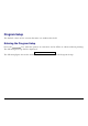
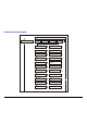
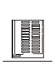
Program Setup The default values of the various functions are indicated in bold. Entering the Program Setup Press the PROGRAM key when the printer is turned on and is offline or online without printing. The following message will be displayed: PRINT OUT? NO The following figure shows the structure and how to move inside the Program Setup.
Main Structure P rint o ut? No P rint o ut? Yes User M acro M acro# 1 Line sp. 6 lpi ... … M acro#4 Line sp. ... M A C R O PA R A M ET ER B L O C K Next M acro? No Next M acro? Yes Config . Me nu No Config . Me nu Yes Hex Dum p No Hex Dum p Yes Low. Jam S ensor Y Tear adjust: 0 Tear adjust: … Upp. Jam S ensor Y Cut adjust:0 Cut adjust: … P arall.
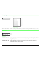
Printout of the Printer Settings PRINT OUT? NO → or ← PRINT OUT? YES ↓ USER MACRO PRINT OUT? NO The Setup is not printed. PRINT OUT? YES The printer setup is printed. The printout starts as soon as you select this value. NOTE: The Program setup printout indicates: • the currently selected values, • the current selected macro is marked with the #x# symbols (USER MACRO #x#), • the current firmware release.
USER MACRO The USER MACRO item allows to prepare four printing environments (MACRO#1, MACRO#2, MACRO#3 and MACRO#4). Each macro is composed of a group of parameters which define a configuration that can then be recalled to easily set the printer for four printing environments. SELECTION OF THE USER MACRO PRINT OUT? NO USER MACRO ↓ ↑ USER MACRO ↓ CONFIG MENU NO → MACRO # 1 → or ← MACRO # 2 → or ← MACRO # 3 → or ← MACRO # 4 → or ← ↓ LINE SP.
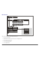
USER MACRO PARAMETERS U ser macro M acro #1 M acro #2 M acro #3 M acro #4 Lin e sp. 6 lpi Lin e sp. ... Lin e sp. Lock N o Lin e sp. Lock Yes Len gth 1 Line Len gth ... Top of F orm 0 Top of F orm ...
R ight M argin 2 R ight M argin … S lash Zero N o S lash Zero Yes P ath Lo w er P ush P ath ... Tear norm al Tear … V T:F F+ C ut V T: ... S tron g im p act S oft im pact P erfo r. S afe N o P erfo r. S afe Yes A utogap 0 A utogap ... Tuning: H oriz 0 Tuning: H oriz ... Tuning: Vert 0 Tuning: Vert ... M acro-> M F G N o M acro-> M F G Yes N ext m acro? N o N ext m acro? Yes C onfig.
Line Spacing MACRO # 1 ↑ MACRO# 1 → LINE SP. 6 LPI → or ← LINE SP. 8 LPI → or ← LINE SP. 12 LPI → or ← LINE SP 3L/30MM → or ← LINE SP 4L/30MM → or ← LINE SP 6L/30MM → or ← LINE SP 8L/30MM → or ← LINE SP 12L/30MM → or ← ↓ LINE SP LOCK NO These values define the line spacing in lines/inch (6, 8, 12) or in lines per 30 mm (3, 4, 6, 8, 12). Line Spacing Lock LINE SP. 6 LPI ↑ LINE SP. LOCK NO → or ← LINE SP. LOCK YES → or ← ↓ LENGTH xxx LINE SP.
Page Length LINE SP. LOCK NO ↑ LENGTH 1 LINE → or ← LENGTH . .. LINES → or ← LENGTH 244 LINES → or ← LENGTH A5 → or ← LENGTH A4 → or ← LENGTH A3 → or ← LENGTH A2 → or ← LENGTH LEGAL → or ← LENGTH LETTER → or ← ↓ TOP OF FORM 0 These items set the page length for fanfold paper in number of lines depending on the current vertical spacing. For the single sheets the page format can be specified in number of lines or the standard formats LETTER, LEGAL, A2, A3, A4, A5.
Top of Form LENGTH Xx ↑ TOP OF FORM 0 → or ← TOP OF FORM ... → or ← TOP OF FORM xxx → or ← ↓ SKIPOVER 0 These items set the top of form. The values range between 0 and the page length - 1. Skip Over Perforation TOP OF FORM 0 ↑ SKIPOVER 0 → or ← SKIPOVER ... → or ← SKIPOVER xxx → or ← ↓ DRAFT MODE NORM These items set the skipover perforation. The values range between 0 and the page length - 1.
Draft Print Mode SKIPOVER 0 ↑ DRAFT MODE NORM → or ← DRAFT MODE BEST → or ← ↓ QUALITY LQ DRAFT MODE NORM The printer performs the draft printing at high speed. DRAFT MODE BEST The printer performs the draft printing at low speed to obtain better quality print. Quality Print Mode DRAFT MODE NORM ↑ QUALITY LQ → or ← QUALITY HS_ LQ → or ← QUALITY NLQ → or ← QUALITY HS_ NLQ → or ← ↓ FONT Draft QUALITY LQ The printer performs the Letter Quality printing.
Font Selection QUALITY LQ ↑ FONT Draft → or ← FONT Courier → or ← FONT Gothic → or ← FONT OCR-B → or ← FONT OCR-A → or ← FONT Script → or ← ↓ PITCH 10 CPI Selects the fonts. OCR-A is displayed only if a non proportional pitch has been selected. Pitch Selection FONT Draft ↑ PITCH 5 CPI → or ← PITCH 6 CPI → or ← PITCH 7.5 CPI → or ← PITCH 8.5 CPI → or ← PITCH 10 CPI → or ← PITCH 12 CPI → or ← PITCH 15 CPI → or ← PITCH 17.
These items set the horizontal spacing in characters per inch. The PROP item sets proportional character spacing.
Pitch Lock PITCH 10 CPI ↑ PITCH LOCK NO → or ← PITCH LOCK YES → or ← ↓ LEFT MARGIN 0 PITCH LOCK NO Setting this item, the pitch can be changed by software or operator panel. PITCH LOCK YES Setting this item, the pitch can be changed ONLY by operator panel. Left Margin PITCH LOCK NO ↑ LEFT MARGIN 0 → or ← LEFT MARGIN ... → or ← LEFT MARGIN xxx → or ← ↓ RIGHT MARGIN 136 The Left Margin is set in number of columns (depending on the current pitch) starting from the physical left edge.
Right Margin LEFT MARGIN 0 ↑ RIGHT MARGIN. 2 → or ← RIGHT MARGIN. ... → or ← RIGHT MARGIN. xxx → or ← ↓ SLASH ZERO NO The Right Margin is set in number of columns (depending on the current pitch) starting from the physical left edge. The default value is 136. Zero Character Printing RIGHT MARGIN 136 ↑ SLASH ZERO NO → or ← SLASH ZERO YES → or ← ↓ PATH LOWER PUSH You can select the Zero character printing with or without a slash.
Paper Path Selection This function defines the default paper path for the current macro.
Tear-Off Mode PATH LOWER PUSH ↑ TEAR NORMAL → or ← TEAR AUTOMATIC → or ← LABEL → or ← TEAR NO → or ← ENABLE CUTTER → or ← ↓ VT: FF+CUT TEAR NORMAL The Tear-Off Function is performed pressing the ONLINE key when the printer is offline. TEAR AUTOMATIC When the printer is not receiving any data, the paper is moved to the Tear-Off position. It is returned to the Tear-Off position as soon as it receives printing data.
Cutter mode This selection appears only if the cutter option is installed. TEAR NORMAL ↑ VT: FF + CUT → or ← VT: LF+CUT → or ← VT: VT → or ← CUT EACH PAGE → or ← CUT PAPER CHANGE → or ← ↓ STRONG IMPACT VT: FF + CUT When the printer receives a VT command, it performs a form feed and then cuts the paper. VT: LF + CUT When the printer receives a VT command, it performs a line feed and then cuts the paper. VT: VT When the printer receives a VT command, it performs a vertical tabulation.
Print Impact Strength VT: FF + CUT ↑ STRONG IMPACT → or ← SOFT IMPACT → or ← ↓ PERFOR. SAFE NO STRONG IMPACT The impact strength of the print head is set for printing on multicopy paper. SOFT IMPACT The impact strength of the print head is set for printing on single paper or few copies. The printing noise is reduced. Paper Perforation This function allows to move the print head aside the paper when the fanfold paper perforation passes between the mylar and the print bar, to avoid paper jams.
Adjusting the Print Head Distance PERFOR. SAFE NO ↑ AUTOGAP -5 → or ← AUTOGAP ... → or ← AUTOGAP +3 → or ← MANUAL GAP → or ← FIXED GAP 0.3 → or ← FIXED GAP ... → or ← FIXED GAP 9.3 → or ← ↓ TUNING.HORIZ 0 AUTOGAP xxx Selecting one of these values sensing the paper thickness. Negative values reduce the distance between the print head and the paper. Default value is AUTOGAP 0. MANUAL GAP Selecting this item, the print head must be adjusted manually.
Horizontal Character Tuning AUTOGAP 0 ↑ TUNING.HORIZ 0 → or ← TUNING.HORIZ ... → or ← TUNING.HORIZ 60 → or ← ↓ TUNING.VERT 0 These values adjust the distance between the left paper margin and the first print character. The values correspond to 1/120 inch units, i.e. the tuning ranges between 0 and 0,5 inch. Vertical Character Tuning TUNING.HORIZ 0 ↑ TUNING.VERT. -30 → or ← TUNING.VERT. ... → or ← TUNING.VERT.
Resetting the Macro Parameters to the Factory Defaults TUNING.VERT. 0 ↑ MACRO -> MFG NO → or ← MACRO -> MFG YES → or ← ↓ NEXT MACRO? NO MACRO -> MFG NO The new values set for the macro parameters will be the used. MACRO -> MFG YES The values set for the macro parameters will be reset to their factory defaults. Selecting Another Macro MACRO -> MFG NO ↑ NEXT MACRO? NO → or ← NEXT MACRO? YES ↓ CONFIG MENU NO ↓ MACRO # 1 To pass over to another macro, select NEXT MACRO YES.
Passing over from one macro to the other then sets two different printing environments. Passing over to the Power-On Configuration At this point of the menu, it is possible to pass over to the Power On Configuration Functions Setting. NEXT MACRO NO ↑ CONFIG MENU NO → or ← CONFIG MENU YES ↓ ↓ HEX DUMP NO PARALL INTERFACE These items are self-explaining.
Adjusting the Tear-Off Position HEX DUMP NO ↑ TEAR ADJUST: - 30 → or ← TEAR ADJUST: ... → or ← TEAR ADJUST: +360 → or ← ↓ CUT ADJUST xxx TEAR ADJUST: xxxx These values adjust the distance between the Tear-Off Perforation and the Tear-Off Bar. The values correspond to 1/180 inch units, i.e. the tuning ranges between -1/6 and 2 inch. 0 is the default value. See also “How to Use the Tear-Off Function”, later in this Chapter.
Storing the values CUT ADJUST: xxxx ↑ STORE? QUIT → or ← STORE? SAVE → or ← STORE? CURRENT → or ← PROG EXIT STORE? QUIT This setting does not save any of the new values set. The values set previously will be used. STORE? SAVE The values set are stored permanently (in the NVM) and will be used until they are changed by the operator. STORE? CURRENT The values set are valid until the printer is turned off. When you turn the printer on again, the values set in the preceding menu setup will be used.
How to Select the Paper Path The paper can be loaded into the printer using different paper paths. The messages indicating the paper paths are shown only if the corresponding loading device is installed on the printer. Proceed as follows: 1. Press the READY key to put the printer offline (the READY indicator is unlit). 2. Press the PATH key, according to the installed devices the following messages are displayed: LOAD LOWER PUSH For the lower push tractor paper path.
How to Use the Tear-Off Function This function is used to match the paper perforation with the tear-off bar. For this function the following values must be set: Selection of the Paper Size 1. Press the PROGRAM key when the printer is disabled or enabled without printing to enter the Program Setup. 2. Press the ↓ key and the following message appears: USER MACRO 3. Press the → key to select the macro for which you want to set the paper size (MACRO#1, MACRO#2, MACRO#3 or MACRO#4). 4.
Adjusting the Tear-Off Position The default value for the Tear-Off Function is TEAR NORMAL. To check the Tear-Off Position proceed as follows: 1. To move the paper to the Tear-Off position, press the ON LINE key when the printer is disabled or enabled without printing. 2. Check if the paper perforation matches the tear-off bar on the printer. If it does not: 1. Press the PROGRAM key to enter the Program Setup. 2. Press the ↓ key until the following message appears: USER MACRO 3.
Selection of the Tear-Off Mode It is now possible to select the Tear-Off Mode. 1. Press the PROGRAM key when the printer is disabled or enabled without printing to enter the Program Setup. 2. Press the ↓ key. The following message is displayed: USER MACRO 3. Press the → key to select the macro for which you want to set the tear-off mode MACRO#1, MACRO#2, MACRO#3 or MACRO#4). 4.
How to Lock/Unlock the Access to the Printer Setups To prevent not expertise persons changing the printer setup parameters, it is possible to lock/unlock the access to the printer setups as follows: • Press ON LINE, MACRO and SHIFT keys at the same time and keep them pressed while powering the printer on. As soon as these keys are released, the following messages will be displayed: 9078 plus or 9078D plus then, LOCKED MENU Now the access to the printer setups is locked.
How to Handle the Paper Parking According to the setting of the TEAR item in the Program Setup, the paper parking procedure is performed in different ways. See the following description: If TEAR NO is selected: TEAR NO • • When the paper is positioned at the first printable line and the paper path is changed (changing the Macro or pressing the PATH key) or the PARK key is pressed, the printer performs automatically the parking procedure.
If TEAR NORMAL is selected: • • • When the paper is positioned at the first printable line and the paper path is changed (changing the Macro or pressing the PATH key) or the PARK key is pressed, the printer performs automatically the parking procedure.
If TEAR AUTOMATIC is selected: • • • When the paper is positioned at the first printable line and the paper path is changed (changing the Macro or pressing the PATH key) or the PARK key is pressed, the printer performs automatically the parking procedure.
If LABEL is selected: • • LABEL When the paper is positioned at the first printable line and the paper path is changed (changing the Macro or pressing the PATH key), or the PARK key is pressed the printer automatically ejects the paper towards the rear of the printer.
If at power on the paper is already loaded in a paper path that is different to the paper path used by the macro which is valid at power-on, independently from the setting of the TEAR function, the display shows TEAR IF NECESS./EJECT PAPER. If the paper to be ejected is longer than 18" tear it off and press the PARK key again to perform the paper ejection. In all the above cases the parking procedure may be interrupted pressing the SHIFT key. The display shows OPER. INTERRUPTED.
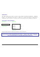
Paper Handling Paper Paths Low er P u sh P ath (90 78 plus a nd 9078D plus) U pper P u sh P ath (90 78D plus) M anua l P ath (90 78 plus) Base C onfiguration W ith Installed O ptions A utom atic Sh eet F eed er plus Low er P u sh Tracto r (90 78 plus a nd 9078D plus) P ush-P ull P ath (90 78 plus a nd 9078D plus) Low er P u sh Tracto r plus C utter (90 78 plus a nd 9078D plus) U pper P u sh Tracto r plus C utter (90 78D plus) 99
Paper Specifications It is important to use the correct paper for obtaining the best performance. See the information table below: Fanfold Paper (9078 plus and 9078D plus models) Loading Mode Lower Tractor Upper Tractor (9078D plus only) Push-Pull (option) Width 76 to 432 mm 3 to 17 inches 76 to 432 mm 3 to 17 inches 76 to 432 mm 3 to 17 inches Length 76 to 609 mm 3 to 24 inches 76 to 609 mm 3 to 24 inches 76 to 609 mm 3 to 24 inches Thickness max.0.635 mm 0.025 inches max. 0.635 mm 0.
Cut Sheets (9078 plus model only) Loading Mode Manual Loading Width 114 to 432 mm (4.5 to 17 inches) Length 101 to 559 mm (4 to 22 inches) Weight Original: 50-120 g/m Multiparts: First Sheet: 55-75 g/m Other Sheets: 45 - 75 g/m Carbon Paper: 14 - 35 g/m A5 149 x 210 mm Portrait & Landscape A4 210 x 297 mm Portrait & Landscape A3 297 x 420 mm Portrait & Landscape A2 420 x 554 mm Portrait Letter 8.5 x 11 inches Portrait & Landscape Legal 8.
Cut Sheets Cut Sheets Loading Modes 9078 plus model Cut sheet loading mode is only available for the 9078 plus model. Cut sheets can be loaded manually, one at a time using the front manual paper path (manual or automatic loading) or automatically using the ASF option for large quantities of paper. Inserting a cut sheet, the fanfold paper is automatically parked with a reverse movement (if the overlapping is not selected).
Loading Cut Sheets 1. Lift the cut sheets support until it locks in horizontal position. 2. Position the left paper guide on the cut sheet support for the first printing column (position 0).
3. Insert a cut sheet along the left paper guide. Match the right paper guide with the sheet margin. 4. The loading mode of the cut sheet depends on the value set for the QUICK function in the Power-On Configuration: Manual loading mode (QUICK NO) Make sure that the printer is disabled. Insert a cut sheet onto the front paper support and press the LOAD/FF key to feed the paper. Press the ON LINE key to enable the printer.
Fanfold Paper Loading Paper Using the Lower Tractor 9078 plus model 9078D plus model If your printer is the 9078 plus model, make sure that the cut sheets support is closed before loading the fanfold paper. 1.
2. Open the tractor area cover turning is upwards and lay it on the top of the printer. • If your printer is the 9078D plus model and it is installed the upper tractor, rotate the upper tractor out of the printer.
3. Unlock the sprockets of the Lower tractor moving the sprocket levers up. Slide the left sprocket to the first printing column. 4. Space the paper guides along the tractor bar.
• If your printer is the 9078D plus model, insert the fanfold paper between the lower and the upper tractor. 5. Hold the fanfold paper in front of the sprockets and insert the paper perforation on the left sprocket pins and close the sprocket cover.
6. Insert the paper on the right sprocket pins, make sure the paper goes under the paper sensor and close the sprocket cover. 7. Match the left sprocket for the first printing position with the ninth position and lock it in place. Adjust the right sprocket gently to remove slack from the paper.
• If your printer is the 9078D plus model, reposition the upper tractor in its initial position 8. Close the tractor area cover. Press the LOAD/FF key to load the paper into the printer.
9. The paper must be loaded as shown in figure (i.e. 9078D plus model).
Loading Paper Using the Upper Tractor 9078D plus model Fanfold paper loading mode through the upper tractor is only available for the 9078D plus model. To load paper in this way, it is necessary to install the upper tractor. See before "Upper Push Tractor Installation" section. 1.
2. Open the tractor area cover turning is upwards and lay it on the top of the printer. 3. Unlock the upper tractor sprockets moving the sprocket levers up. Slide the left sprocket to the first printing column.
4. Space the paper guides along the tractor bar. Open the sprocket covers of the left and right sprocket. 5. Hold the fanfold paper in front of the sprockets and insert the paper perforation on the left sprocket pins and close the sprocket cover.
6. Insert the paper on the right sprocket pins, make sure the paper goes under the paper sensor and close the sprocket cover. 7. Position the left sprocket for printing and lock it in place. Adjust gently the right sprocket to remove slack from the paper.
8. Close the tractor area cover. Press the LOAD/FF key to load the paper into the printer. 9. The paper must be loaded as shown in figure.