Operation Manual Compur Statox 4120
Compur Statox 4120 This document is subject to changes without notice. Regular updates can be viewed on our web site www.compur.com You are welcome to communicate any proposal how to improve this document to Compur Monitors. Copyright Compur Monitors GmbH & Co. KG Published by: Compur Monitors GmbH & Co. KG Weissenseestrasse 101 D-81539 München Tel. 0049 (0) 89 62038 268 Fax.
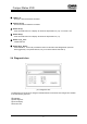
Compur Statox 4120 Contents Seite 1. 2. 2.1 2.2 2.3 2.4 3. Important notice The Statox 4120 System: Purpose of use and description 4 4 Statox 4120 sensor head Statox 4120 rack Statox 4120 control module Diagnostic box 5 6 8 9 Installation and electrical connections 10 Statox 4120 sensor head 10 3.1.1 Mounting 10 3.1.
Compur Statox 4120 1. Important notice Statox 4120 is an explosion proof system for the detection of toxic gases. It can be operated in hazardous areas classified division 1 and 2. Before installing and putting Statox into operation read and observe this manual! To operate the system safely, observe this manual carefully. It must be operated and maintained by qualified and authorised personnel. No other application than ambient air monitoring of the gas specified is authorised by the manufacturer.
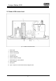
Compur Statox 4120 2.1 Statox 4120 sensor head pic.
Compur Statox 4120 pic. 2: Statox 4120 sensor head for Cl2 und ClO2 Operation principle Ambient air enters the sensor (2) by diffusion through an opening at the bottom. The sensor creates a current - signal proportional to the gas concentration. This signal is amplified, temperature compensated and linearised. As a digital signal it is transmitted to the control module. To protect the sensor from being poisoned by a high gas concentration, the Statox features a built – in air purge.
Compur Statox 4120 Construction: The system consists of a 19“-4-HE rack with backplane and up to nine Statox 4120 control modules. Each Statox 4120 sensor head is communicating with one control module.
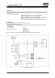
Compur Statox 4120 2.3 Statox 4120 control module Each Statox 4120 Control module has its own power supply. The intrinsically safe sensor head supply circuit is supplied by a separate secondary winding. pic.
Compur Statox 4120 LED A1 (9) - On if pre - alarm threshold is exceeded Display A2 (10) - On if main alarm threshold is exceeded Button A1 (4) - Press and hold button A1 to display A1 threshold. Adjust with Pot. (12). A1 must be < A2. Button A2 (3) - Press and hold button A2 to display A2 threshold. Adjust with Pot. (11). Button T (5) „Test“ - Initiates self test. Button R (6) „Reset“ - Rests Alarms A1, A2 und SF provided the reason for the alarm has disappeared.
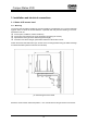
Compur Statox 4120 3. Installation and electrical connections 3.1. Statox 4120 sensor head 3.1.1. Mounting The sensor head should be installed as close as possible to potential leaks. If it is used as industrial hygiene device it should be located between a potential leak and personnel working in the area.
Compur Statox 4120 pic.7: Drilling plan for the mounting brackets 3.1.2. Connecting the signal cable The signal cable connects sensor head and control module. Use only shielded cable. The maximum cable length depends on the cable specifications. Cable: Length l Capacity CL [pF/m] Inductivity LL [mH/m] Approved parameters: UO, IO, CO, LO Approved parameters: Ui, Ii, Ci, Li Conditions: UO < Ui and IO < Ii and l x CL < CO - Ci and l x LL < LO - Li pic.
Compur Statox 4120 Example of cable specifications: Max. cable capacity: l x CL = Co - Ci = 107 nF Max. cable inductivity: l x LL = Lo - Li = 6,6 mH Diameter: > 0,75 mm2 The Statox 4120 Systems will work reliably if the electrical resistance is : RL < 50 Ω. Most commonly the maximum length is limited by the cable capacity. Example: Cable diameter is 1,0 mm2 (0,04 in), CL = 90 pF/m, LL = 0.7mH/km, RL / km = 19,5 Ω.
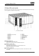
Compur Statox 4120 3.2 Statox 4120 rack Statox 4120 Rack must not be installed in hazardous areas. Observe local safety- and installation regulations. Protect any cable from tensile strain. The five - and the nine - contact terminals are plugged in. They can be removed to ease wire connection. pic.10: Backplane Statox 4120 Rack Installation instructions: The signal cable from sensor head to backplane must be shielded.
Compur Statox 4120 Installation instructions for the RFI-shielded Statox 4120 rack: Use well shielded signal cable. The shield must make good contact with the RFI resistant cable glands. It must not be interrupted by connection boxes. If the signal cable is run through such, these must also be equipped with RFI resistant cable glands. They must be installed isolated from ground, and the shield must make good contact with the metal housing of the box.
Compur Statox 4120 Slide switch S1: S1 ON 1 Relay active during alarm A2 2 Relay active during alarm A1 OFF Relay inactive at alarm A2 Relay inactive at alarm A1 Toggle switch S3: S3 1 2 3 4 5 6 7 ON Detection mode Rest Alarm by resetbutton R Detection mode Detection mode Measured value accepted if logic signal is 0V Detection mode Detection mode 8 Detection mode OFF auto - reset Modem - and analog signal adjustment for service only! Delete EPROM for service only! Ex works settings 3.
Compur Statox 4120 DIP switch S1 (see pic. 8) programs gas and measuring range. If you change your Statox to another gas or measuring range, a hardware modification may be required and the electronics must be re adjusted. This must be done by authorised personnel.
Compur Statox 4120 Table 4: Switch position for Cl2 Measuring range: S1/1 S1/2 S1/3 S1/4 S1/5 S1/6 S1/7 S1/8 E-PROM Index sensor head E-PROM Index control module 0-1,5 ppm ON ON ON ON ON ON OFF ON 12, 13, 14 02, 03 0-3 ppm ON ON ON OFF ON ON OFF ON 12, 13, 14 ≥ 02 Measuring range: S1/1 S1/2 S1/3 S1/4 S1/5 S1/6 S1/7 S1/8 E-PROM Index sensor head E-PROM Index control module 0-150 ppm ON ON ON ON ON OFF OFF ON 12, 13, 14 ≥ 02 0-10 ppm OFF ON ON ON OFF ON OFF ON 12, 13, 14 02, 03 Table 5: Switch position
Compur Statox 4120 Table 8: Switch position for SO2 Measuring range: S1/1 S1/2 S1/3 S1/4 S1/5 S1/6 S1/7 S1/8 E-PROM Index sensor head E-PROM Index control module Table 9: Switch position for NO2 0-0,5 ppm OFF ON ON OFF ON ON ON ON 21 04 Measuring range: S1/1 S1/2 S1/3 S1/4 S1/5 S1/6 S1/7 S1/8 E-PROM Index sensor head E-PROM Index control module 0-15 ppm ON ON ON ON ON ON ON ON 21 04 4. Compur Statox 4120 operation 4.
Compur Statox 4120 4.5 Manually triggered self test of the system Push and hold button T for 2 s to initiate a self test. The next self test will start automatically after 24 h. 4.6 System failure As soon as the Statox detects a faulty system condition the LED SF goes on and relay SF is activated. This will be the case if: Self test not passed Data transmission faulty No signal 5. Trouble shooting As soon as the Statox detects a faulty system condition the LED SF goes on and relay SF is activated.
Compur Statox 4120 5.1 Using the diagnostic box Switch the diagnostic box on. Then connect it to the opto- coupler receptacle on sensor head bottom. Keep the LED`s and the phototransistors of the opto- coupler clean for proper data transmission. 5.1.1 Operation and error codes of the diagnostic box Note: If a combination of push button operations is requested ( f. i. ST + ENT), the buttons must be operated in a short time distance. Example: ST + ENT initiates a self test.
Compur Statox 4120 5.1.2 Status messages of the sensor head Button ST scans the system status: Code Status and action required Passed System OK. Error A1 Amplifier defective: Repeat adjustment or replace pcb. Error B1 Error B2 Check battery pack connection. Battery pack discharged or defective, replace. If battery pack discharges frequently, check charging circuit. Battery pack voltage drops under load. Error PU Pump energy consumption too high. Replace.
Compur Statox 4120 6. Maintenance and calibration 6.1 Inspection Statox 4120 Sensor head The following maintenance intervals are general recommendations. Specific applications may request different intervals.
Compur Statox 4120 Filter cartridge replacement Remove tube Remove filter cartridge and bearing Clean air access opening Replace filter cartridge and bearing Replace tube Generator cell replacement Disconnect generator cell, remove tube to pump Remove generator cell Replace generator cell Replace tube Connect generator cell 6.2 Sensor head calibration 6.2.
Compur Statox 4120 Procedure: Remove splash guard and replace it by test gas adapter. Connect span gas cylinder. Do not open regulator yet! Connect diagnostic box to sensor head. Reading diagnostic box: Red LED flashing; - “ready” – “x.xxx ppm” Push CAL button Reading diagnostic box: “CALIBR” Push ENT button Reading diagnostic box: “ppm = ?” Enter span gas concentration in ppm. Reading diagnostic box: ppm = „value“. If you have entered a wrong value push button CE and repeat.
Compur Statox 4120 7. The maintenace request option Purpose: This option can differentiate between fatal errors in the sensor head and maintenance requirements. It requires a Statox 4120 control module equipped with EPROM Index ≥ 03. It also sets the analog output to 4 mA during the self test, if required. Operation modes: The Statox 4120 can operate in 9 different modes. The relevant mode can be seen by the control module LED`s and relays.
Compur Statox 4120 Error C3 (Too low sensitivity during self test): S3/3 on the control module offers the option to choose if C3 shall be a maintenance request (position ON) or system failure (position OFF). The system failure messages A1 and C3 (both defined as SF): The sensor head still transmits measured values to the control module, but these measured values will not be displayed on the bar graph display nor be transmitted to the analog output.
Compur Statox 4120 pic.12: Electrical connections and short circuit contacts Short circuit contacts on the maintenance request pcb: Bridge 1 2 3 4 5 6 7 Analog 0-1V Analog 4-20 mA ● ● Analog 4(0)-20mA* ● ● ● ● ● ● ● ● * Analog output 0 mA, if PCS-relay active, f. i. during self test, alarm threshold adjustment and if the diagnostic box is connected. In any other case 4-20 mA.
Compur Statox 4120 8. The option analog output inhibition This option inhibits the analog output if the logic signal of the control module (see pic. 3, terminal 11) is set to 5 V instead of 0 V. This is the case if the system is unable to provide a valid measured value, for instance if: - Alarm thresholds are adjusted or displayed - During self test - During the diagnostic box is connected - During system start.
Compur Statox 4120 9. The option zero adjustment This option is available for COCl2 sensor heads with measuring range 0.3 ppm only. The zero adjustment of the sensor is started via diagnostic box. System requirements: Sensor head EPROM index 18c, control module EPROM index 03a, diagnostic box EPROM index 02. A zero adjustment must only be done in clean air. It is started with the buttons ZERO + ENT. It should be done before starting a calibration. The set zero value is not visible.
Compur Statox 4120 10. Technical data General: Gas Cl2 CO COCl2 HCN HCl H2S ClO2 NO2 SO2 Accuracy at TLV: Alarms: RFI: Manufacturer: Measuring range 0-1.5 ppm, 0-3 ppm, 0-10 ppm 0-150 ppm 0-0.1 ppm, 0-0.3 ppm, 0-0.5 ppm, 0-1.5 ppm, 0-15 ppm, 0-100 ppm 0-15 ppm, 0-30 ppm, 0-50 ppm, 0-100 ppm 0-100 ppm 0-30 ppm, 0-50 ppm, 0-100 ppm 0-0.
Compur Statox 4120 Control module: Type: Operating temperature: Storage temperature: Explosion protection : Operating environment: power: Supply voltage: Max. operating voltage Uo: Max. operating current Io: Max. external capacity Co: Max. external inductivity Lo: Display: Analog output: Relays: 5331 0x0 (115 / 230 VAC) -20 to +40 oC -30 to +60oC [EEx ib] IIC II 2 G 15 W per control module 115 / 230 VAC 22 V DC 50 mA DC 162 nF 6.6 mH Bargraph 4-20 mA / 400 Ω max.
Compur Statox 4120 11. Accessories and spare parts Art. Nr.
Compur Statox 4120 558435 518330 506947 557874 562197 502052 550700 551695 554483 508413 558856 561199 562544 506921 506897 551976 503845 577849 505311 507036 532828 STATOX Manual -ESTATOX Sensor head battery STATOX Sensor head bearing 236 mm STATOX Sensor head EPROM "12" STATOX Sensor head EPROM "13" STATOX Sensor head EPROM "14" STATOX Sensor head EPROM "15" STATOX Sensor head EPROM "17" STATOX Sensor head EPROM "18" STATOX Sensor head EPROM "18c" STATOX Sensor head EPROM "19" STATOX Sensor head EPROM "
Compur Statox 4120 Specifications are subject to change without notice, and are provided only for comparison of products. The conditions under which our products are used, are beyond our control. Therefore, the user must fully test our products and/or information to determine suitability for any intended use, application, condition or situation. All information is given without warranty or guarantee.