Installation Manual By Firstech LLC, Version: 1.0 Applicable to the following control modules: - CM4200-DX (remote start) - CM5200 (DT remote start with Blade) - CM4000 (alarm and remote start) - CM5000 (DT alarm and remote start with Blade) - CM4300 (alarm) This device complies with Part 15 of the FCC rules. Operation is subject to the following conditions; (1) This device may not cause harmful interference.
Table of Contents Introduction ............................................................................................................................................... 3 Kit Contents............................................................................................................................................... 3 Installation Basics ....................................................................................................................................
Introduction Thank you for purchasing this Firstech system for your vehicle. The following installation manual is intended for experienced and authorized Firstech technicians. We highly recommend that you contact your local Firstech dealer and seek professional installation. Call 888-820-3690 or visit our websites at www.compustar.com or www.firstechllc.com to locate your nearest dealer. This installation manual is for both CM4 Series and CM5 Series control modules.
Installation Basics If you are new to installing Firstech Series Remote Starts and / or Alarms, we highly recommended that you thoroughly review this manual to installing your first unit. Key Points to Consider Before Installation: You must code remotes to this system before anything will function Program remotes by cycling the ignition ON / OFF five times within seven seconds and tap button 1 (0.5 seconds) on the first remote, and then tap button 1 (0.5 seconds) on the second remote.
Remote Programming Routine IMPORTANT: Any and all remotes must be coded to the control module prior to performing any and all operations. Remotes excluding P2WSSR STEP 1: Activate programming mode by manually turning the vehicle’s key between the Ign On and Off (or the Acc & On positions) five times within 7 seconds. The vehicle’s parking lights will flash once with the successful completion of this step.
Placement and Use of Components IMPORTANT: The placement and use of components are critical to the performance of this system. Antenna and Cable Antenna Firstech antennas are calibrated for horizontal installation at the top of the windshield. The cable that connects the antenna to the control module must be free from any pinches or kinks. Installing the antenna in areas other than the windshield may adversely affect the effective transmitting distance of the remotes.
significant difference in sensitivity for both 1st and 2nd stages. Recommended dial settings for most vehicles is somewhere between 2 & 4. Siren (CM4000, CM5000, and CM4300 Only) The volume output of the siren can be increased 3 dB by cutting black wire loop located near the base of the siren. To adjust duration time when the alarm has been triggered, change Option 3-07 – the system default is 30 seconds.
You Must Have the OP500 Option Programmer To set auxiliary outputs on the control module involves the new Programmable Output Connector wires (POCs). You must choose two odd pin wires on the black 18 pin connector that you are not using. For example we will use POC 8 and 9. STEP 1: Plug in OP500 and use the Right or Left Arrow Button to scroll through the menu to POC 8 and POC 9 on LCD Line 1.
STEP 1: Change Option 2-10 to setting 3 - No tach sensing. STEP 2: Process complete – there is no further programming required other than adjusting crank time when necessary (see below). Adjusting Crank Time: To adjust minimum crank times, refer to Option 2-12. To help ensure successful starting, the system will automatically add additional crank time to the 2nd and 3rd start attempts. In addition, there is a built in “Smart Resting Mode”.
STEP 3: Exit the vehicle and close the door. The vehicle’s engine should shut off upon closing the door. If the vehicle’s engine does not shut off, check the door trigger connection or wait for the factory domelight to go out. The Firstech system is in reservation mode and the vehicle is ready to safely remote start. Additional Notes Reservation mode will be cancelled if the control module recognizes the vehicles door, hood or trunk opening – or if the alarm is triggered.
CM5200 Wiring Schematic (Remote Start) The CM5200 is the control module for all remote start units. This controller is universal regardless of remote or antenna type.
CM4200-DX Wiring Schematic (Remote Start) The CM4200-DX is the control module for all remote start units. This controller is universal regardless of remote or antenna type. 1 Red 2 Green / White 3 Red/White 4 White CN1 Green Loop Cut=Auto Trans. Uncut=Manual Trans.
CM5000 Wiring Schematic (Alarm and Remote Start) The CM5000 is the control module for all alarm and remote start combo units. This controller is universal regardless of remote or antenna type.
CM4000 Wiring Schematic (Alarm and Remote Start) The CM4000 is the control module for all alarm and remote start combo units. This controller is universal regardless of remote or antenna type. 1 Red 2 Green / White 3 Red / White 4 White CN1 5 Violet 6 Yellow 7 Green and Red 8 Black CN2 CN3 Green Loop Cut=Auto Trans. Uncut=Manual Trans.
CM5200, CM4200-DX, CM5000 and CM4000 Wiring Description Connector 1 (CN1), 8-Pin Pin 1 Red - Constant 12V positive (+) power input. This wire must be connected. The proper vehicle wire will test (+) 12V at all times - while the key is in the off position, the on position and during crank. Pin 2 Green/White – This is a dual-purpose wire that features selectable functionality thru the trunk/light jumper on the control module. It is either a positive (+) parking light output or positive (+) trunk output.
There are two wires coming off of the relay; yellow-black and yellow. To utilize the anti-grind or starter-kill features, the vehicles starter wire must be cut in half, otherwise, cut the relay out of the harness and connect the yellow (Pin 6) directly to the vehicles’ starter wire. IMPORTANT: For anti-grind and starter-kill applications, the yellow wire goes to the starter side of the vehicles starter wire and the yellow/black goes to the key side. Pin 7 Green – Ignition 12V positive (+) output and input.
Pin 3 Red/Black [POC 2] – 2nd Starter 250mA negative (-) output. This output can be used to trigger the pre-wired relay located on the main ignition harness. Pin 4 Light Blue/White - Brake 12V positive (+) input. This input must be connected as it provides a shut down for the remote start. The proper wire will test (+) 12V while the foot brake is pressed. Pin 5 Green [POC 3] - 2nd Ignition 250mA negative (-) output. This output can be used to trigger the pre-wired relay located on the main ignition harness.
Pin 14 Yellow/Black - Engine sensing input. This wire is connected to the vehicles Tach or Alternator wire and is required if you are not using the no tach sense setting. IMPORTANT: To change engine-sensing modes, you must change Option 2-10; Default requires a Tach input. Pin 15 White [POC 8] - Horn honk 250mA negative (-) output. This is an optional output that will pulse the factory horn. The proper wire will show ground (-) while the horn is sounding.
Pin 1 Black - L.E.D negative (-) ground. Pin 2 Black/White- L.E.D. 3V positive (+) output. Connector 6 (CN6), 4-Pin (Pre-wired Shock Sensor) Pin 1 Black - Negative (-) ground. Pin 2 White - 2nd stage negative (-) input. (Instant trigger) Pin 3 Red - 12V positive (+) output. Pin 4 Yellow - 1st stage negative (-) input. (Warn away) Connector 7 (CN7), 4-Pin (Pre-wired RPS) Pin 1 Black - Negative (-) ground. Pin 2 White - Negative (-) paging input. Pin 3 Red - 12V positive (+) output.
Pin 1 Gray/Black - Negative (-) ground. Pin 2 Gray – 3V positive (+) L.E.D. output. Pin 3 Gray – Negative (-) output. Connector 10 (CN10), 4-Pin (Optional Sensor Input) This connector provides optional sensor inputs. Most commonly used with proximity and tilt sensors. Pin 1 Black – Negative (-) ground. Pin 2 Black/White - 2nd stage negative (-) input. (Instant trigger) Pin 3 Red – 12V positive (+) output. Pin 4 Grey/White - 1st stage negative (-) input.
CM4300 Wiring Schematic (Alarm) The CM4300 is the control module for all alarm units. This controller is universal regardless of remote or antenna type.
CM4300 Wiring Description Connector 1 (CN1), 4-Pin Pin 1 Red - Constant 12V positive (+) power input. This wire must be connected. The proper vehicle wire will test (+) 12V at all times - while the key is in the off position, the on position and during crank. Pin 2 Green/White – This is a dual-purpose wire that features selectable functionality thru the trunk/light jumper on the control module. It is either a positive (+) parking light output or positive (+) trunk output.
Pin 1 Green/White [POC 1] - Parking light 250mA negative (-) output. The proper wire will test (-) when the parking light switch is in the on position. Pin 2 Violet/Black - Trunk negative (-) input. This is an optional input that will monitor when the vehicle’s trunk has been opened. The proper wire will provide a (-) trigger while the trunk is open. Pin 3 Orange [POC 6] - Factory Arm 250mA negative (-) output. This is an optional output that will provide a (-) pulse during lock.
Pin 11 Violet/Black - 250mA negative (-) output when armed. This wire is pre-wired to the starter-kill relay. Caution: When this wire is being used to trigger aftermarket accessories it must be diode isolated. Pin 12 Not used The rest of the connectors on the CM4300 are the same as the CM5000 and CM4000. Please see the CM5200, CM4200-DX, CM5000 and CM4000 Wiring Description for those details.
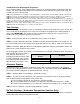
OPTION GROUP 1 Feature Default Setting - I Optional Setting - II Optional Setting - III Optional Setting - IV Lock After Shutdown Only 1-01 Unlock before, Lock after, starting Off On Lock After Remote Start Only 1-02 Lock / Unlock pulse duration 0.8 sec 2.5 sec 0.125 sec 3.
OPTION GROUP 4 Feature Default Setting - I Optional Setting - II Optional Setting - III Optional Setting - IV 4-01 Aux 1 output 0.5sec Latch 20 sec Program 4-02 Aux 2 output 0.
Option Menu Descriptions Only uncommon options are described in this section. 1-03 Driver’s Priority Unlock - The driver’s door must be isolated from the other doors. Use the Orange/Black CN4 as your 2nd Unlock output. 1-04 Double Pulse Unlock – This feature cannot be used with Option 1-03. This feature provides a double pulse on the blue unlock wire. 1-05 Rearm Output – Optional settings to change the event trigger on the orange rearm wire. 1-06 Reservation Lock – Manual transmission only.
Option 4: Will start once every 24 hours if the temperature falls below Option settings 2-08 or above Option settings 209. For example, if you want your car to start and run 25 minutes when the temperature falls below 32°F, you need to set up the following options: 1) Option 2-05 (Cold Start) turned on, 2) Option 2-06-IV (24 hr.
3-10 Valet – This option changes valet modes. Default 1: Key on/off five times or remote valet (I + III for 0.5 seconds) with key in the on position. Option 2: Key on/off five times or remote valet (I+III for 0.5 seconds) – key does not need to be in the on position. Option 3: Secure valet: RPS Valet or remote valet (I+III for 0.5 seconds) – this option prevents the system from being put into valet via key on/off five times.
4-11 Bypass Brand Through RS232 Port – Default setting allows for compatibility with ADS Idatalink modules. Setting 2 changes compatibility to Fortin bypass modules. This is only available on the CM5000 and CM5200. Special Option Groups 1 & 2 IMPORTANT: The OP500 is required to change settings in Special Option Groups 1 and 2. Special Option Group 1 1 Diesel Timer – Option 2-03 must first be set to setting 2. This special option allows a specific wait to start time (in seconds) to be programmed.
Following the auxiliary and diesel settings (if selected), the POC options will be displayed on the OP500. The POCs can be set between 0 (default) and 19. All are only available on the CM5000. STEP 3: When finished with the adjustment of the various option settings, press and hold the “W” (write) button until the OP500 chirps, which is approximately 2.5 seconds. This will write the settings to the control module. Wait until the module displays “Success” before disconnecting it from the antenna cable.
STEP 3: Once finished scrolling through the menu wait for the parking lights and/or siren chirp to confirm the option number. i.e. option 2-04 will flash 4 times. Then use one of the table selections to select the option corresponding to your desired setting. Resetting to Factory Defaults: To reset the options in a particular menu group, enter the menu shown in the above tables. To reset options with a 2 Way remote tap button 3 three times.
I have these control modules that say MM720 and MM721. What are they? A: These control modules are the new CM5 series. MM720 = CM5000 and MM721 = CM5200. I am trying to program the control module with the OP500 Option Programmer and it flashes “ER 01” when I plug it in to the antenna cable. What should I do? A: Make sure that the system is not locked/armed. The last thing to check is the antenna cable or antenna extension cable – make sure this is not damaged. If you need to, try another cable.
The vehicle starts and shuts down 3 times in a row. A: This usually means that the engine sensing mode is not working correctly. If you are using a coil, change to an injector or try alternator mode. The vehicle will lock and unlock, but will not remote start or flash the parking lights. A: The system is in valet mode. Tap buttons (I) + (III) for 0.5 seconds while the key is in the on position. Whenever I try to arm the vehicle, it chirps the siren 3 times and will not arm.
Technical Support Contacts Firstech technical support is reserved for authorized dealers only. Monday - Friday 888-820-3690 (7:00 am – 5:00 pm Pacific Coast Time) Email support@compustar.com Web http://www.compustar.com click on “dealer support” Wire Diagrams Click on the “Installogy Access Client” link found on your desktop. If you are a qualified dealer and unable to access this site, call your sales representative or the number above.